


Gas turbine engines power airplanes and power plants. Inside the engine, the gas is extremely hot. This extreme heat can melt the metal turbine blades. To stop this, engineers use a smart method called film cooling. They push cold air through tiny holes in the blade. This cold air creates a thin blanket over the metal surface. Sometimes, normal straight holes do not spread the air well. So, engineers use a special shape to make the air spin. This is called swirling film cooling. The spinning air spreads wider and protects more of the blade.
If you want to design safer and better engines, studying professional heat transfer CFD simulation projects is the best step. In this tutorial, we will use ANSYS Fluent to look directly inside the engine. We will study the exact physics of how the cold air spins and cools the hot metal.
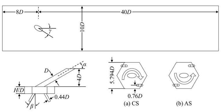
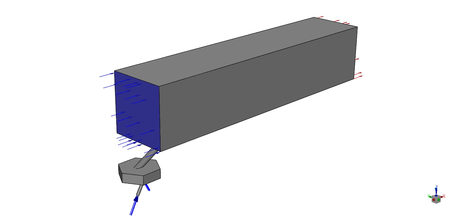
Figure 1: The exact schematic showing the dimensions of the main channel and the hexagonal swirl chamber.
Simulation Process: The Mesh and the Physics Models
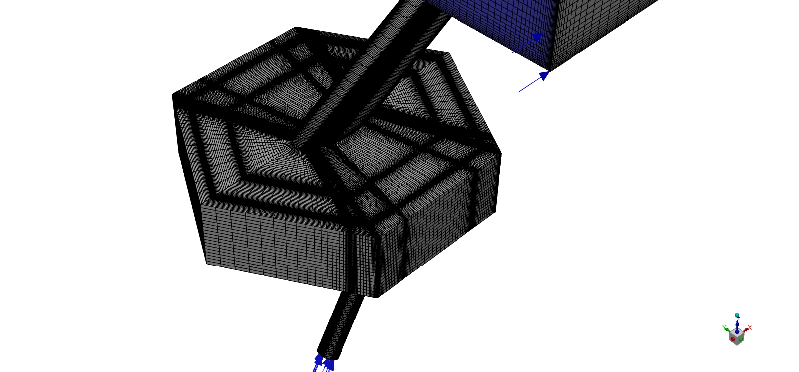
To build this simulation, we must set up the shape and the physics rules correctly. First, we build the 3D shape and fill it with a grid. This specific six-sided shape forces the air to bounce off the walls and start spinning before it even leaves the hole. We use ANSYS ICEM CFD to make a fully structured grid using exactly 6,078,788 hexahedral cells. also use a special O-grid pattern around the round holes.
Second, we set the rules for the air. The main engine air flows over the top at a fast 20 m/s and a cold temperature of 293 K. The special cooling air shoots out of the bottom nozzle at 19 m/s with a warm temperature of 320.15 K. We turn on the species transport model. We use this physics tool to track the exact oxygen (O2) and nitrogen (N2) gas molecules. This tool mathematically proves exactly how much the cooling jet mixes with the main engine air as they travel down the pipe.
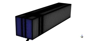

Figure 2: The 3D structured grid using exactly 6,078,788 hexahedral cells to capture the boundary layer accurately.
Post-processing: Physics of Swirling Jet Flows
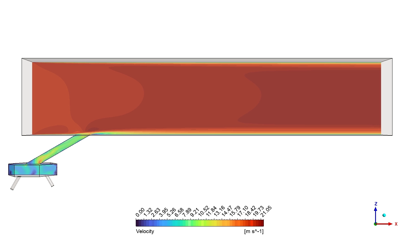
Now we will analyze the scientific visual data exactly as the software calculated it. We will study the fluid speed, the flow paths, and the exact heat spread based purely on the four provided images. First, we examine the Velocity contour from the side view. The legend proves the Velocity ranges from exactly 0 to 21.05 m/s. The main top air is dark red, which means it moves very fast. The cooling air travels up the tilted green tube. When the cooling jet shoots out of the hole, it hits the fast main air. The main air forces the jet to bend down. Look closely behind the hole. You will see a thin dark blue layer. This blue color means the Velocity drops to near 0 m/s. This is a low-pressure wake zone. The fast main air jumps over the jet, creating a slow, quiet space behind it. This slow wake zone helps pull the cooling air down to the solid floor.
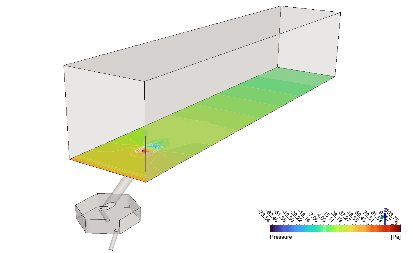
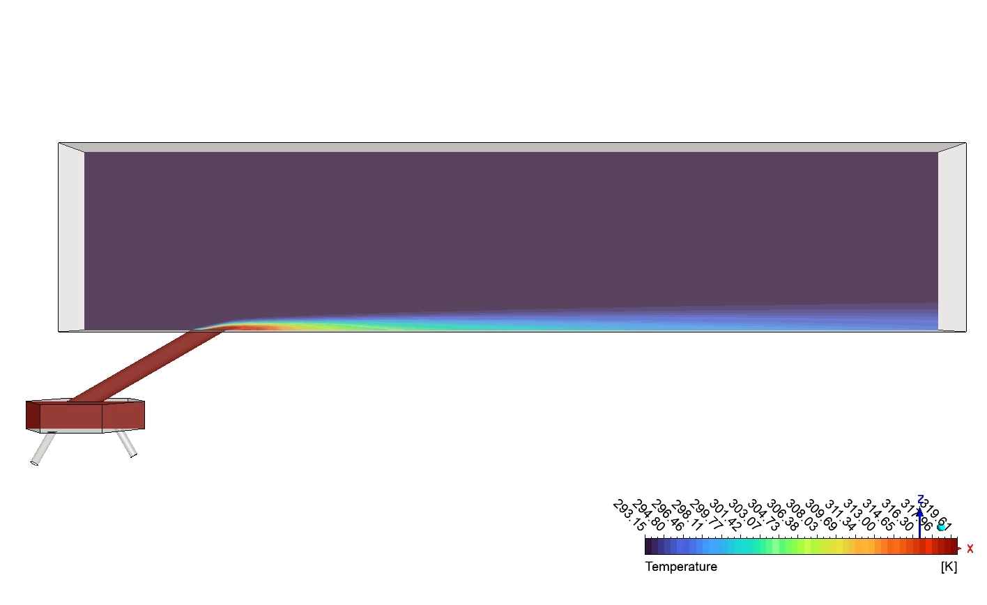
Second, we study the Temperature contour from the top view. The legend goes from exactly 293.15 to 319.61K. The hole looks like an ellipse on the floor. The cooling gas exits the hole as a bright red and orange shape. This is the hottest part of the jet at exactly 319.61K. Because the gas is spinning, it does not stay in a thin straight line. The swirling energy forces the red shape to spread out wide to the sides. As the gas moves far to the right, the color slowly turns to yellow, then green, then light blue. This proves the spinning jet slowly and safely mixes with the dark purple main air over a very large area.
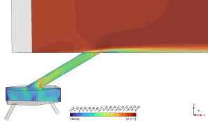
Figure 3: The side Velocity contour showing a slow blue wake region behind the jet, with a maximum speed of 21.05 m/s.

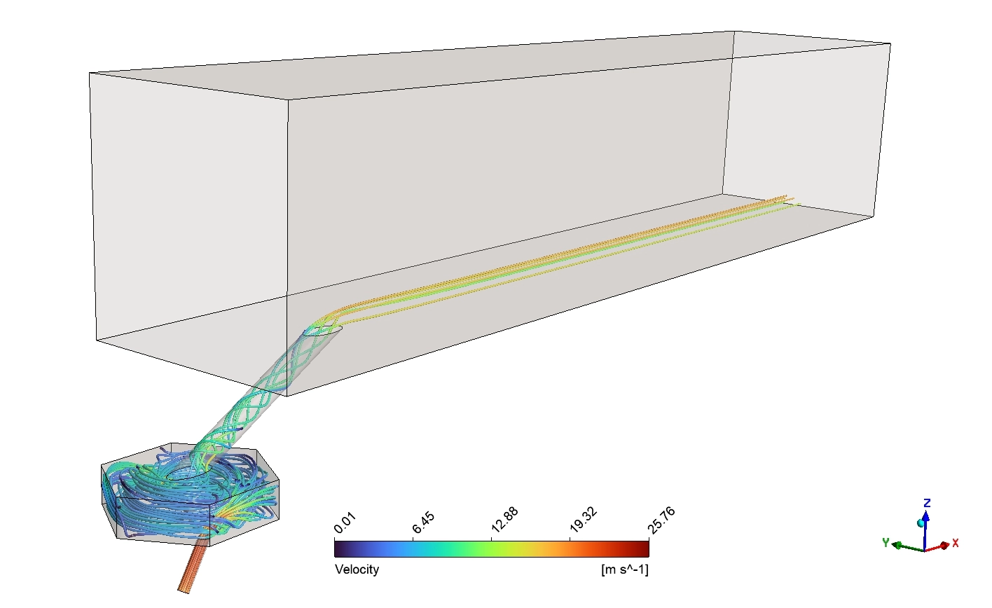
Figure 4: The 3D Velocity streamlines showing the spinning vortex in the chamber and a peak speed of 25.76 m/s

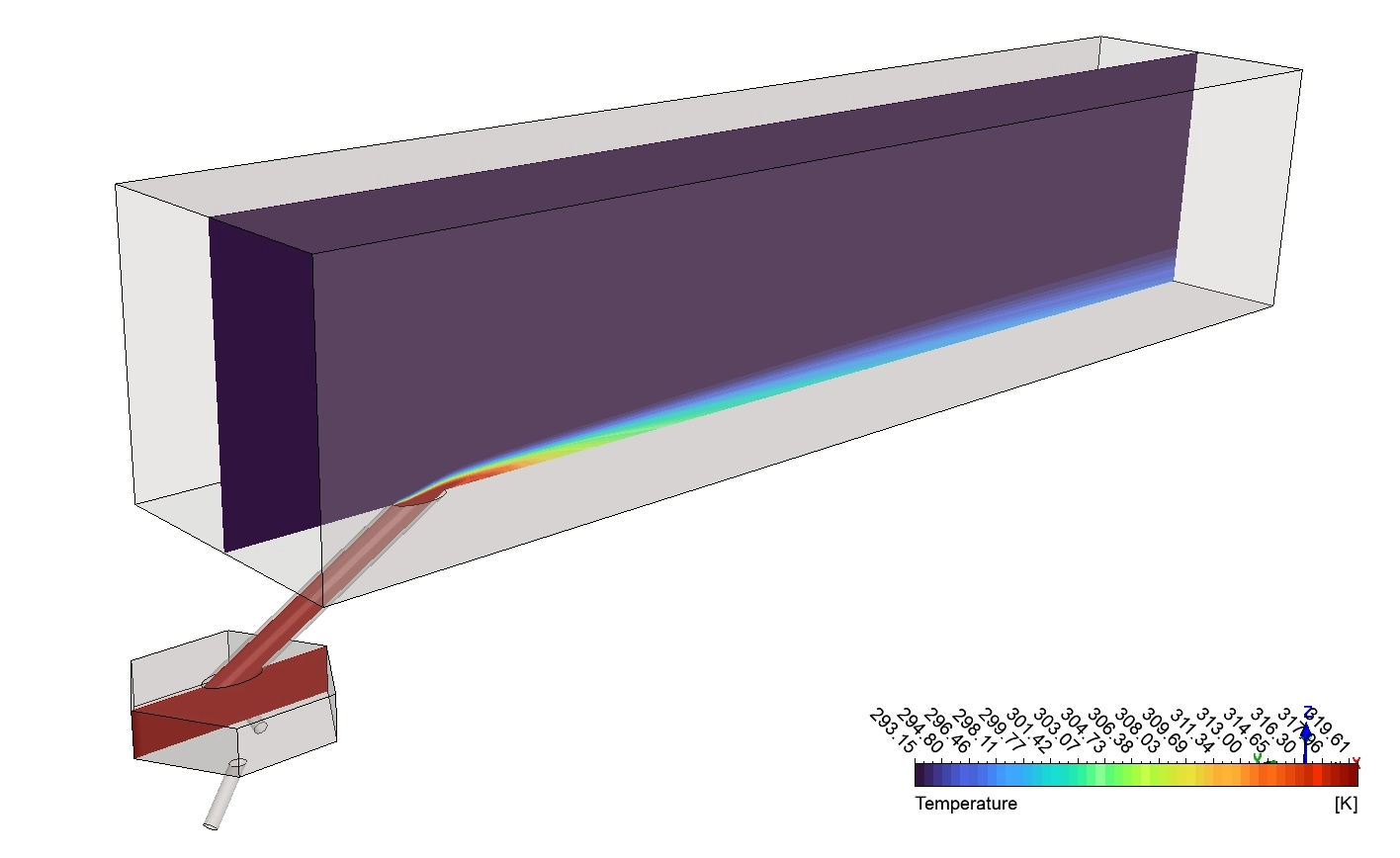
Figure 5: The side Temperature contour proving the jet bends perfectly to form a thin thermal blanket against the bottom wall.
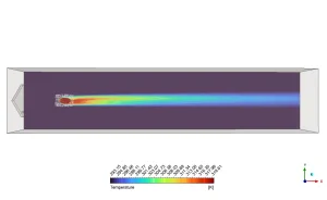
Figure 6: The top Temperature contour showing the wide lateral spread of the jet from 319.61 [K] down to 293.15 [K].
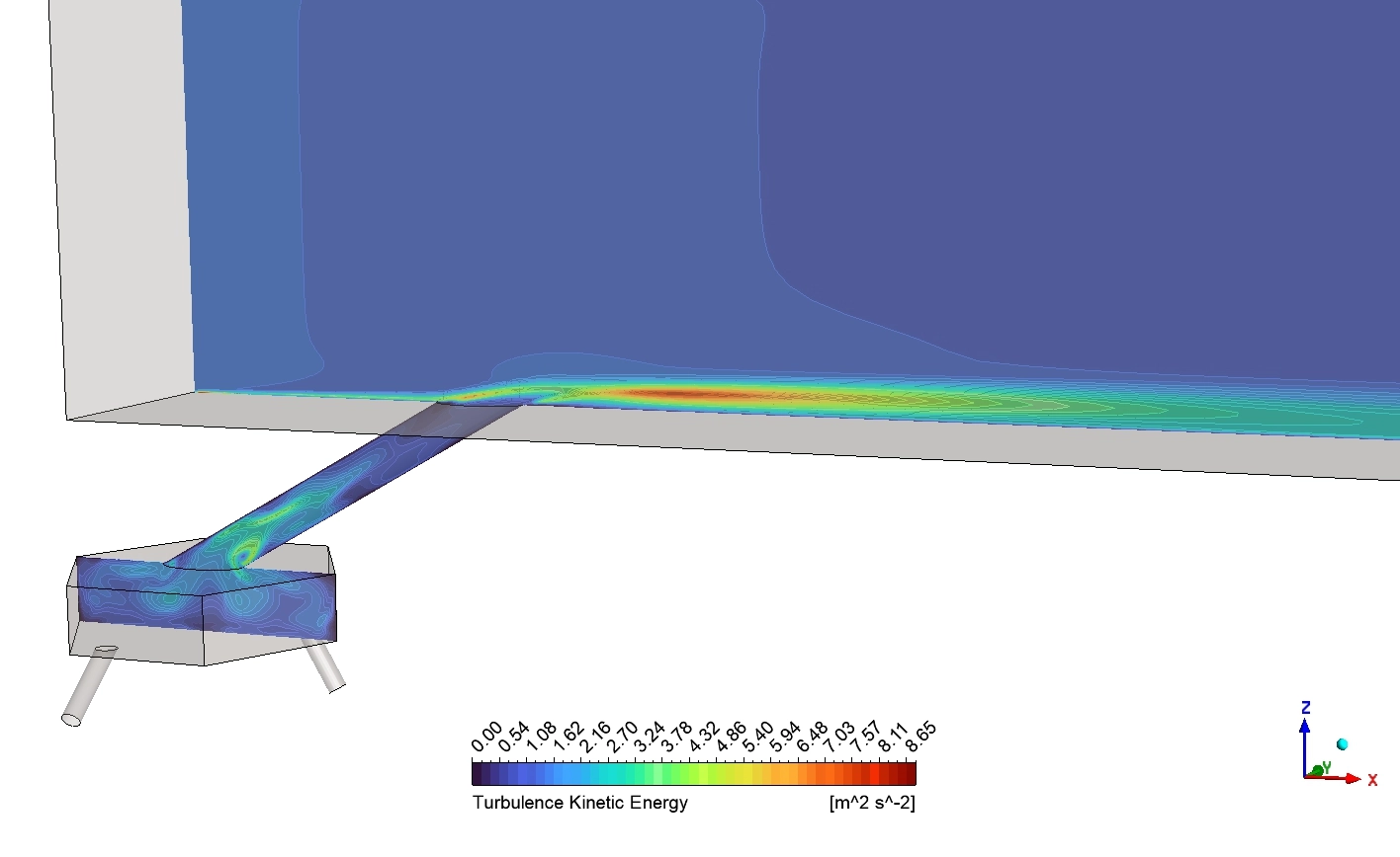
Next, we look at the Temperature contour from the side view. This is the most important proof of film cooling. The main engine air is dark purple, sitting at exactly 293.15 [K]. The cooling jet is bright red. Watch what happens when it leaves the tilted tube. The red color does not shoot straight up into the purple air. Instead, it bends perfectly and lays completely flat against the bottom line. It creates a thin, highly visible green and blue layer that hugs the floor for a very long distance. This proves the swirling jet successfully creates a tight thermal blanket that prevents the main air from touching the metal.
Finally, we analyze the 3D Velocity streamlines. The legend shows a maximum fluid speed of exactly 25.76m/s. Look at the very bottom. The air enters through a thin orange pipe. Because the pipe is small, the air moves at its highest speed here. The air enters the hexagonal box. A hexagon has exactly six flat walls. When the fast air hits these sharp corners, it is forced to twist and turn into a violent circle. You can see the blue and green lines forming a tight tornado. This spinning tornado travels up the tube and exits onto the floor. The lines stay flat and parallel to the ground. The spinning momentum stops the air from flying away, ensuring perfect wall protection.
Frequently Asked Questions (FAQ)
- Why does a low-velocity wake form behind the hole?
- When the cooling jet shoots out, it acts like a solid rock blocking a river. The fast main air hits the jet and jumps over it. This creates a quiet, slow-moving space directly behind the hole. The Velocity drops near zero. This slow wake actually helps pull the cooling air flat against the floor.
- Why is it important that the jet stays flat against the wall?
- If the cooling jet flies high up into the main air, it leaves the metal floor completely naked. The extreme engine heat will melt the naked metal. The jet must lay flat to act as a physical shield between the metal blade and the hot engine gas.


Reviews
There are no reviews yet.