


A Two-stage Ejector Refrigeration System is a special way to create cooling without using much electricity. Instead of a normal compressor with moving parts, this system uses a fast jet of hot steam to do all the work. The ejector works like a vacuum cleaner. Its fast-moving steam pulls in a slower fluid from the part of the system that needs to be cooled (the evaporator). Having two stages makes the whole system work much better than a single-stage design, which helps save a lot of energy. This Two-stage Ejector CFD study uses computer simulation to look inside and see how it works, based on a reference paper [1].
- Reference [1]: Dong, Jing-Ming, et al. “Numerical investigation of miniature ejector refrigeration system embedded with a capillary pump loop.” Micromachines8 (2017): 235.
Figure 1: Schematic of the Two-stage Ejector Refrigeration System analyzed in the CFD study [1].
Simulation Process: Fluent Setup, Meshing and Modeling the Ejector System
Because the two-stage ejector is perfectly round, we can use a smart trick and simulate only half of it as a 2D model to save computer time. We filled this shape with a very neat grid of structured quadrilateral cells to get accurate results. The water vapor inside the ejector moves at very high speeds, so it gets squeezed and its density changes. To capture this correctly, we used the ideal-gas model, which is perfect for this type of compressible flow. We also carefully set the boundary conditions to make sure the flow moves forward smoothly through both ejector stages without any backflow.
Figure 2: The 2D geometry model used for the Two-stage Ejector Fluent simulation
Post-processing: CFD Analysis, Visualizing the Flow Field and Thermal Performance
The temperature contour reveals the cooling magic that results from this high-speed flow. As the steam expands and speeds up in the nozzles, its temperature drops dramatically. The incoming steam starts at 333.2K, but in the core of the mixing chamber, the temperature plummets to a very cold 173.1K. That is a massive temperature drop of over 160K! This extreme cooling is a direct result of the fluid’s energy being converted from pressure to speed. The most important achievement of this simulation is the successful and accurate capture of the combined fluid dynamics and thermal effects across both stages. This proves our model can reliably predict the performance of these complex, energy-saving cooling systems, which is critical for designing more efficient refrigerators and air conditioners.
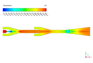
Figure 3: Temperature distribution from the Refrigeration System Ejector CFD simulation, highlighting the significant cooling effect.
The velocity contour provides a clear visual of the engine driving the refrigeration system. High-pressure steam enters the first nozzle and accelerates to an incredible speed, reaching a maximum of 147.5 m/s. This high-speed jet creates a powerful suction effect that pulls in the first stream of refrigerant. The process repeats in the second stage, creating another zone of high-speed flow to pull in more refrigerant. This contour clearly shows the “roller coaster” pattern of the flow speeding up in the narrow nozzles and then slowing down in the wider diffuser sections. This careful control of speed is what makes the whole system work.
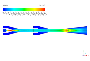
Figure 4: Velocity field from the Two-stage Ejector Refrigeration System CFD analysis, showing supersonic jets and flow deceleration.


Reviews
There are no reviews yet.