

In the automotive industry, passenger comfort is a primary design goal. A modern vehicle requires an efficient climate control network to deliver hot or cold air into the cabin. This network relies on a complex arrangement of plastic tubes and vents hidden behind the dashboard. To ensure the air travels smoothly to the passengers’ faces and feet, engineers perform a detailed Automotive HVAC Duct System CFD analysis. By conducting a highly accurate Automotive HVAC Duct System fluent simulation, designers can clearly observe the invisible airflow before manufacturing physical parts. Please note that this specific report is an educational demonstration of fluid dynamics and is not a validation study. A complete CFD Analysis of Automotive HVAC Duct System helps manufacturers locate blocked air channels and improve overall thermal comfort. Inside the simulation software, engineers can measure the exact air velocity and temperature at every single vent. Calculating these parameters accurately requires advanced computational methods and a deep understanding of fluid mechanics. To learn how to set up these complex air conditioning simulations for your own engineering projects, please explore our detailed HVAC tutorials.
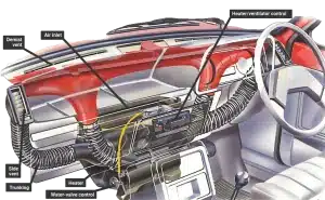
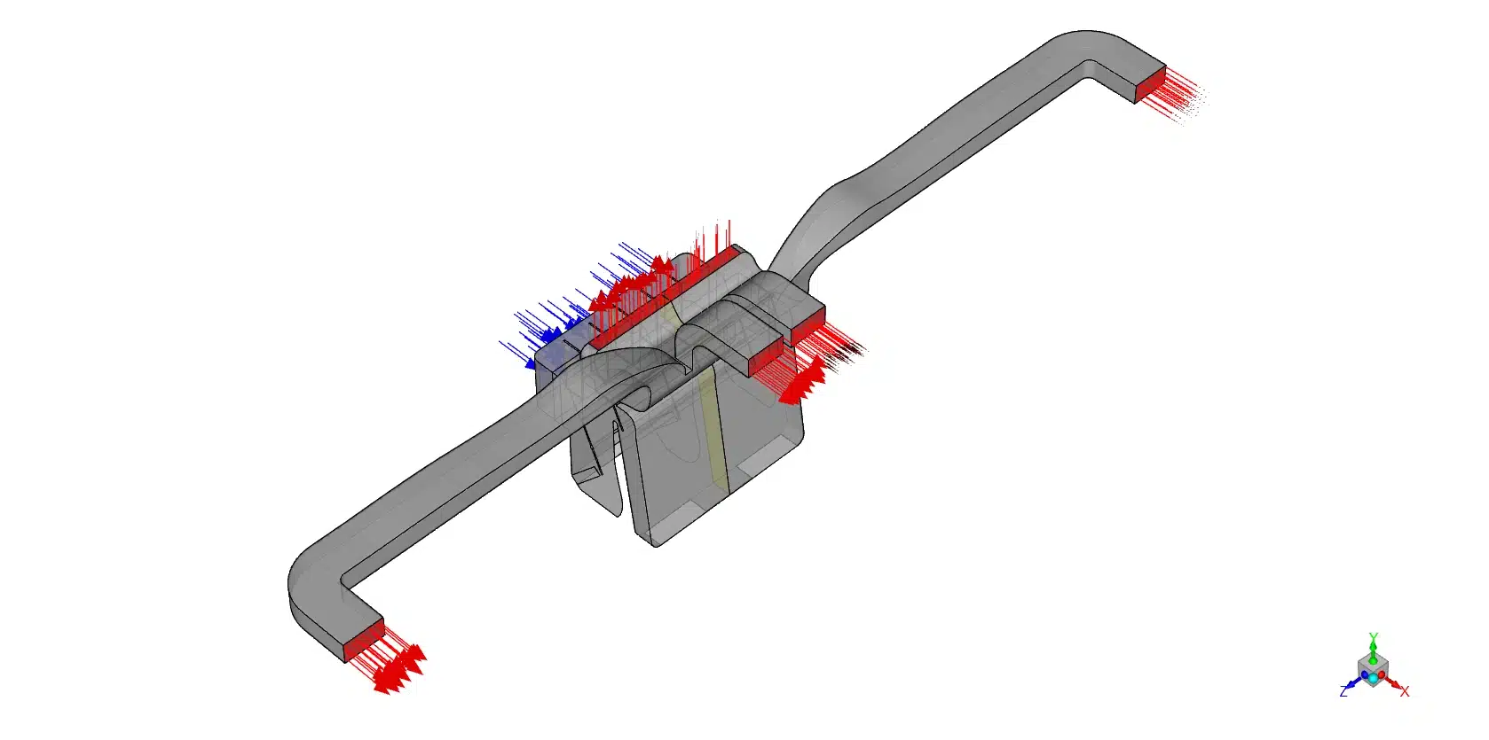
Figure 1: A schematic drawing of the virtual geometry, showing the main blower inlet and the multiple exit branches inside the dashboard.
Simulation Process: Geometry and Tetrahedral Mesh Generation
To begin this Automotive HVAC Duct System ANSYS Fluent project, we constructed a complete 3D computational representation of the dashboard duct network. This virtual geometry includes the central blower inlet and several exit branches leading to the windshield, face, and feet. Next, we used the ANSYS meshing tool to divide the empty interior space into exactly 2,623,865 tetrahedral cells. We set the main inlet to inject warm winter air at exactly 310 K (37°C) with a slow, steady velocity of 0.5 m/s. Furthermore, we defined all outer plastic walls as completely adiabatic boundaries. This means no thermal energy escapes through the plastic into the surrounding dashboard.
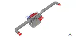
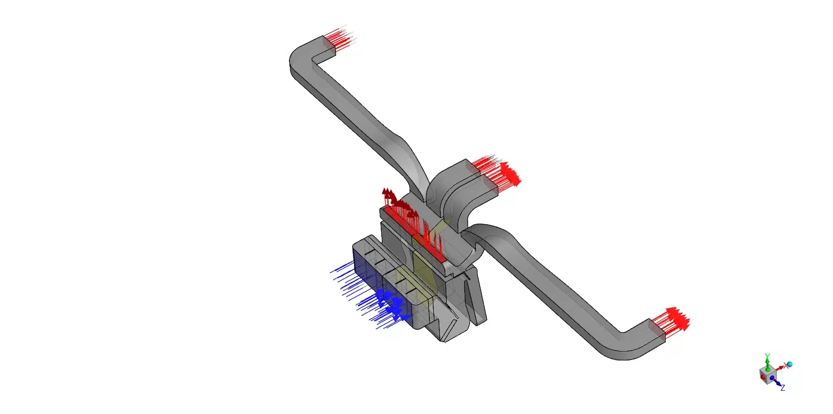
Figure 2: The 3D computational representation displaying the tetrahedral mesh structure and the inflation layers near the walls.
Post-processing: Analysis of Airflow Distribution and Vent Velocity
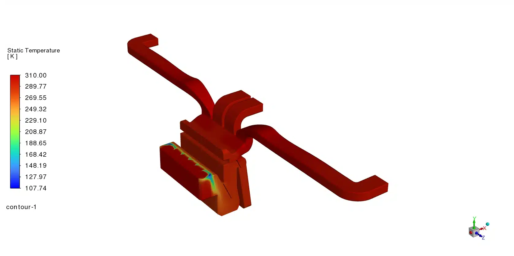
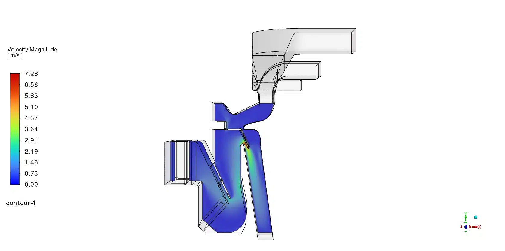
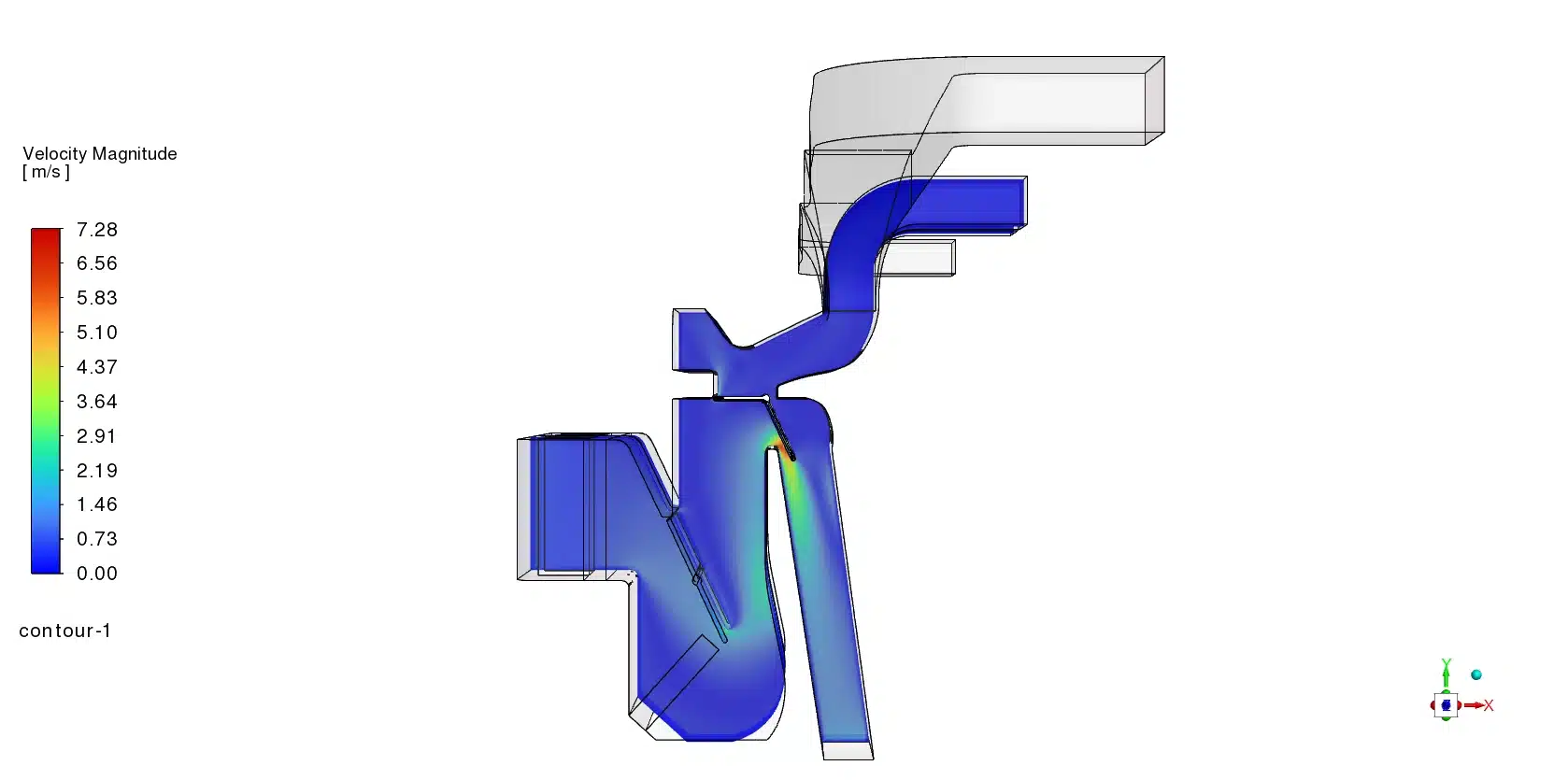
To evaluate the true engineering performance of this climate control design, we must deeply analyze the mathematical velocity data and the visual temperature contours together. The attached temperature contours reveal exactly how the climate control unit mixes the hot and cold air. Inside the central chamber, we observe a distinct and problematic separation of thermal energy. The contour displays deep blue zones representing the very cold incoming air at 273.00 K. Simultaneously, we see dark red zones representing the hot air heated to 310.00 K. Instead of blending into a uniform, comfortable green color, the two air streams separate heavily. This physical event is called thermal stratification. The hot 310 K air naturally rises and fills the upper plastic tubes, turning them bright orange (around 300 K to 306 K). Conversely, the heavier cold air falls toward the bottom sections, creating light green and blue zones (around 280 K to 290 K). This uneven temperature distribution is a severe engineering failure because it means different vents will blow air at completely different temperatures into the cabin.
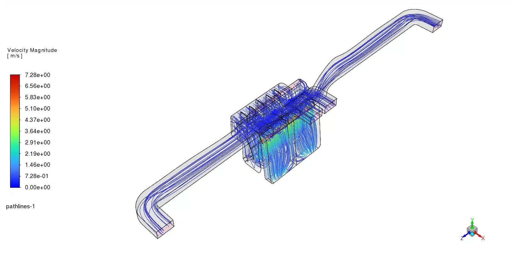
Next, we must examine the exact vent velocities in the data table to see where this poorly mixed air travels. The software calculated a severe flow imbalance inside the tube network. The table shows an extremely high air velocity of 2.2317 m/s at the outlet-foot-left and outlet-front-mid.1 locations. In fluid mechanics, moving air always follows the path of least physical resistance. These specific tubes are likely very wide, very short, or highly straight, allowing a massive volume of air to rush through them effortlessly. However, the fluid physics behave very poorly for the side window vents. The solver measured an incredibly slow velocity of 0.0750 m/s at the outlet-front-side-left. This proves that the internal tube leading to the side window is heavily restricted by sharp twists or narrow walls. This geometric restriction creates a massive pressure drop, choking the airflow completely. Finally, the windshield defrosting vent receives a moderate velocity of 0.4079 m/s, which is generally too slow to melt thick winter ice safely and quickly.
| Outlet Location | Area-Weighted Average Velocity | Unit |
| outlet-foot-left | 2.2317 | m/s |
| outlet-front-mid | 0.1433 | m/s |
| outlet-front-mid.1 | 2.2317 | m/s |
| outlet-front-side-left | 0.0750 | m/s |
| outlet-windshield | 0.4079 | m/s |

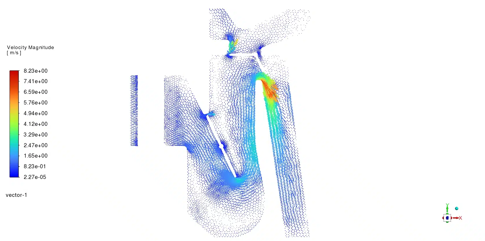
Figure 3: Velocity pathlines showing the strong airflow escaping rapidly to the foot vents and the restricted, choked flow toward the side vents.
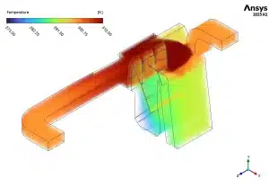
Figure 4: 3D volume temperature contour highlighting how the upper ducts receive warmer orange air while the lower sections trap colder blue and green air.
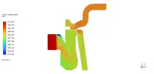
Figure 5: Static temperature contours displaying severe thermal stratification, where the cold 273 K air (blue) fails to mix completely with the hot 310 K air (red).
When we combine the severe thermal stratification from the visual contours with the extreme flow imbalance from the data table, the engineering conclusion becomes perfectly clear. This specific duct design provides terrible passenger thermal comfort. Because of the thermal separation and flow imbalance, a driver might feel a harsh, strong blast of cold air at their feet, while their face receives almost zero warm airflow. To optimize this computational representation, mechanical engineers must place physical mixing baffles inside the central chamber. These baffles will force the blue and red air to crash together and blend completely. Furthermore, engineers must reduce the physical diameter of the foot tubes to increase resistance, while widening the side tubes to reduce pressure drop. These simple geometric changes will balance the physical airflow and deliver perfectly mixed, comfortable air to every single passenger in the vehicle.
Frequently Asked Questions (FAQ)
- What is thermal stratification in an HVAC system?
- A: Thermal stratification happens when hot air and cold air fail to mix properly. The hot air rises to the top, and the cold air falls to the bottom. This is a big problem because the vents will blow different temperatures at the passengers.
- What does an adiabatic boundary condition do?
- A: An adiabatic boundary is a mathematical setting in ANSYS Fluent. It means that absolutely zero heat energy can pass through the solid material. In this simulation, the air does not lose any heat to the surrounding plastic dashboard.
- Why does the foot vent have a velocity of 2.23 m/s while the side vent has 0.07 m/s?
- A: Air naturally flows where there is less physical resistance. Because the foot vent tube is wider and straighter than the side vent tube, the air easily rushes out of the foot vent. The narrow side vent creates a high pressure drop, causing very slow airflow.


Reviews
There are no reviews yet.