


A Windcatcher CFD simulation is a computer model of a traditional building feature used for natural cooling. This passive cooling simulation shows how architecture and engineering can work together. A Windcatcher Fluent analysis is a type of building performance simulation that helps us see how wind can be used to ventilate a room without using any electricity. This is a key part of CFD in architecture, where we study how air flows around buildings. This work is based on the methods in the invaluable research paper, “Analysis of traditional windcatchers and the effects produced by changing the size, shape, and position of the outlet opening” [1], ensuring our analysis is reliable.
- Reference [1]: Varela-Boydo, C. A., S. L. Moya, and R. Watkins. “Analysis of traditional windcatchers and the effects produced by changing the size, shape, and position of the outlet opening.” Journal of Building Engineering 33 (2021): 101828.

Figure 1: Windcatcher CFD simulation
Simulation Process: Fluent Setup, SST k-ω Model for Architectural Aerodynamics
o perform this External Aerodynamics CFD study, every setting was carefully chosen for accuracy.
- Geometry and Mesh: The windcatcher and building geometry were created in SpaceClaim. To correctly model the wind, we created a very large computational domain around the building. We used Fluent Meshing to generate a high-quality polyhedral mesh. A grid independence study was performed to ensure the results were not affected by the mesh size. After testing five different grids, Grid #4 with 3,752,563 cells was selected, as it provided stable results with an acceptable error of less than 5%.
- Physics and Solver: We used Fluent’s pressure-based solver. Based on the reference paper [1], the SST k-ω turbulence model was chosen. This model is excellent for this type of simulation because it accurately predicts how the air will flow both far away from and very close to the building’s walls.

Figure 2: The detailed 3D geometry of the building and windcatcher used for the Building Performance Simulation.

Figure 3: The grid independence study graph for the Windcatcher Fluent analysis, which confirms the accuracy and reliability of the simulation results.
Post-processing: CFD Analysis, Airflow Capture and Ventilation Performance
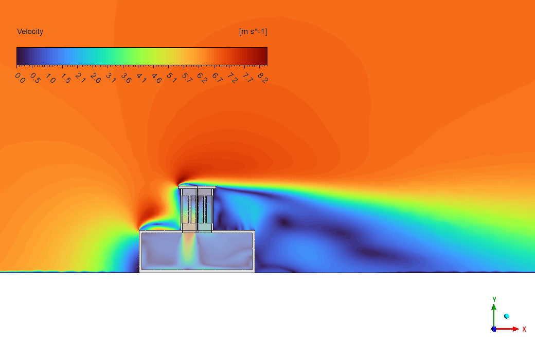
The velocity contour provides a professional visual that acts as a diagnostic tool for the windcatcher’s operation. From an engineering standpoint, it confirms the device’s primary function: it effectively “catches” the wind. The visual shows a high-speed airflow pattern on the windward side of the building, with wind velocity reaching 8.2 m/s. This is the energy source for the entire system. The windcatcher’s large opening is perfectly positioned to intercept this high-energy air and channel it down into the building. This is not just a random effect; it is a deliberate engineering design captured perfectly by the simulation.
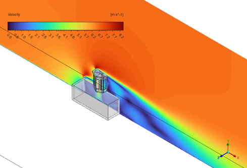
Figure 4: A professional velocity contour from the Natural Ventilation CFD study, showing how the windcatcher effectively captures external airflow.
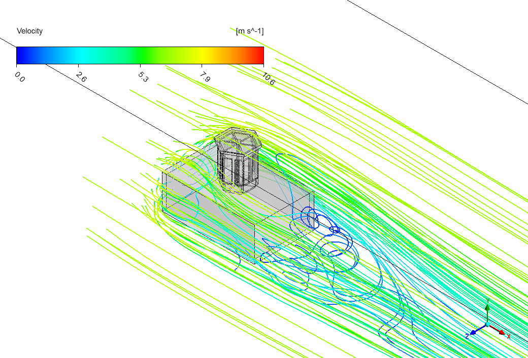
The simulation also reveals a more detailed engineering story about comfort and efficiency. As the high-speed air is directed down into the room, it slows to a gentle breeze between 0 and 2 m/s. This is the key to successful passive cooling: it brings in fresh outside air but slows it down enough to be comfortable for people inside. The simulation also shows a low-velocity “wake” region behind the building. This low-pressure area helps to pull stale air out of the building through other openings, creating a complete and continuous ventilation cycle. The most important achievement of this simulation is its ability to demonstrate the full ventilation process—from capturing high-velocity external wind to delivering comfortable, low-velocity fresh air into the living space—proving the windcatcher’s design and giving architects a validated tool to create zero-energy cooling solutions.


Figure 5: A professional visual of 3D and 2D air streamlines from the Passive Cooling Simulation, illustrating the complete ventilation path from outside to inside.


Reviews
There are no reviews yet.