
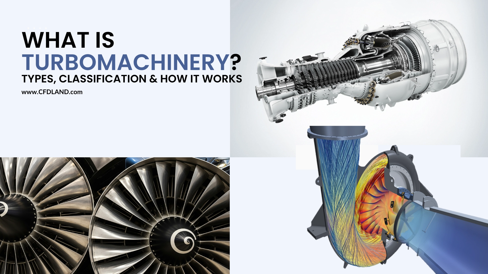
Turbomachinery is a special branch of engineering that deals with moving fluids and rotating parts. The word comes from the Latin word turbo, which means a spinning object. In simple terms, a turbo machine is any device that adds energy to a fluid or takes energy out of a fluid using a spinning shaft. we need to first know the basics of how these machines work, how they are classified, and the physics behind them.
What Is Turbomachinery Used For?
Engineers rely on these machines in almost every modern industry to transport fluids or generate mechanical power. When people ask what is turbomachinery used for, the answer ranges from everyday household items to massive industrial plants.
In the power generation industry, large steam turbines and gas turbines extract energy from hot fluids to produce electricity for entire cities. In the aerospace sector, jet engines use a series of compressors and turbines to create thrust and fly airplanes across the globe. In the oil and gas industry, heavy-duty pumps move liquids through long pipelines, while industrial compressors manage natural gas flows. Even in our homes, small water pumps and air conditioning fans function using the exact same physical principles. Because they offer high efficiency and continuous energy transfer in a compact size, they are the standard choice for handling any flowing liquid or gas.
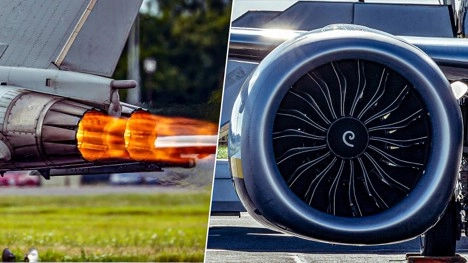
Figure 1: The jet engines on modern commercial airplanes are highly complex turbomachines that include both pump (compressor) and turbine sections
Classification of Turbomachines
Because there are so many different designs, engineers use a specific classification of turbomachines to select the correct equipment for a project. We can classify these machines based on four main physical characteristics:
- Energy Transfer: This defines the main purpose of the machine. Power-absorbing machines, like fans and compressors, require an external motor to add energy to the fluid. Power-generating machines, like turbines, extract energy from the fluid to rotate a shaft and generate power.
![(a) A pump supplies energy to a fluid, while (b) a turbine extracts energy from a fluid. [Fluid Mechanics: Fundamentals and Applications by Yunus A. Çengel, John M. Cimbala]](https://cfdland.com/wp-content/uploads/2026/07/2-4.webp "image of What Is Turbomachinery? Types, Classification & How It Works")
Figure 2: (a) A pump supplies energy to a fluid, while (b) a turbine extracts energy from a fluid. [Fluid Mechanics: Fundamentals and Applications by Yunus A. Çengel, John M. Cimbala]
- Flow Direction: This describes how the fluid travels through the internal blades. In axial flow machines, the fluid travels parallel to the central rotating shaft. In radial flow machines, the fluid moves perpendicularly outward from the center. Mixed flow machines use a combination of both paths.
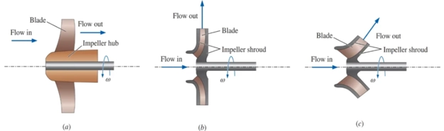
Figure 3: The impeller (rotating portion) of the three main categories of dynamic pumps: (a) axial flow, (b) centrifugal flow, and (c) mixed flow,
- Fluid Type: The machine geometry must match the working fluid. Gas turbomachines handle compressible fluids like air or steam. Liquid turbomachines handle water or oil. Multiphase machines can handle complex mixtures of liquids and gases.
- Enclosure Type: Open-flow machines, such as helicopter rotors and wind turbines, operate freely in the open environment without an outer shell. Enclosed-flow machines, such as industrial pumps, keep the fluid strictly contained inside a solid metal casing to control the internal pressure.
To wrap it up, Figure 2 shows them in a simple classification:
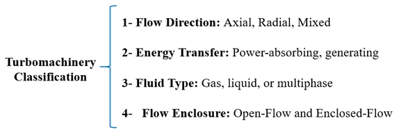
Figure 4: Turbomachinery: Types of classification
How Turbomachinery Works (The Physics)
we have to look at the interaction between the moving and fixed parts to understand how any turbo machine works. Almost every machine has a rotor and stator. The stator is the stationary part that guides the fluid at the correct angle. The rotor is the spinning part that actually transfers the energy.
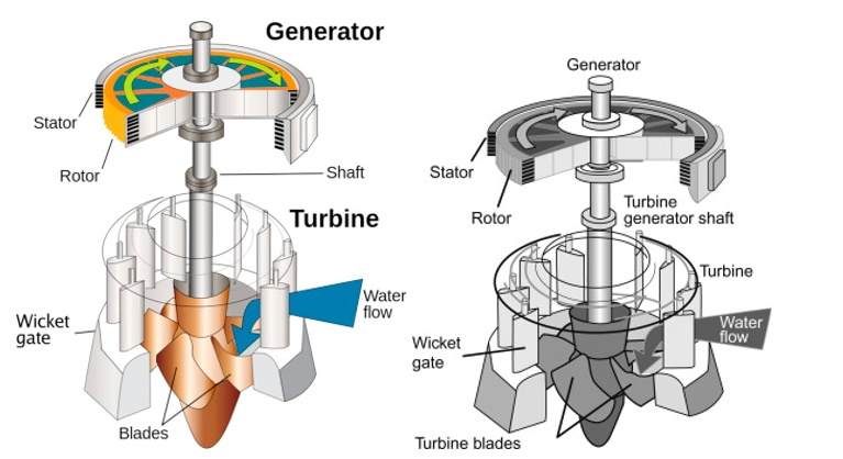
Figure 5: These show examples of turbomachine with the static stator part and the rotating roto component – taken from Encyclopedia of Physical Science and Technology
Because the blades are moving at the same time the fluid is flowing, engineers use a geometric tool called the velocity triangle. This triangle shows the mathematical relationship between the absolute speed of the fluid, the speed of the spinning blade, and the relative speed of the fluid as it passes over the blade. By studying the velocity triangle, designers can shape the blades perfectly so the fluid hits them smoothly without losing energy.
The amount of energy transferred between the fluid and the rotor is calculated using the Euler turbomachine equation. This is the most fundamental physical law in turbomachinery design. The equation proves that the mechanical work done depends entirely on how the fluid’s angular momentum changes as it travels from the inlet of the rotor to the outlet.
Engineers also measure the degree of reaction to understand the pressure changes inside the machine. This parameter explains how much of the total fluid pressure drops (or rises) inside the moving rotor compared to the fixed stator.
Finally, for systems that use hot gases, the entire physical process is governed by the brayton cycle. In a brayton cycle turbine (like an airplane engine or gas power plant), air is compressed, heated with fuel, and then sent through the turbine section. The hot gas expands rapidly, pushing against the rotor blades to generate massive amounts of power.
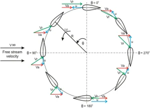
Figure 6: A velocity triangle illustrates the relationship between fluid speed and blade speed, which is essential for calculating energy transfer using the Euler turbomachine equation. This is an example for a wind turbine rotor taken from Investigation on fixed pitch Darrieus vertical axis wind turbine
Main Types of Turbines & Compressors
When we need to select a specific turbine type for an industrial project, we look at the working fluid and the required power output. Steam turbines extract energy from high-pressure water vapor and are the core of most thermal power plants. Gas turbines operate on the brayton cycle and are widely used in aviation and modern power generation. Hydraulic turbines, such as Pelton or Francis models, extract energy from flowing liquid water in dam power plants.
Compressors perform the opposite function by adding pressure and velocity to gas-phase fluids. An axial flow compressor uses alternating rows of rotating and stationary blades to push air straight through a central channel. Because they can process massive amounts of air very efficiently, they are the standard choice for jet engines. On the other hand, centrifugal compressors push the gas outward from the center and are very common in industrial refrigeration and natural gas pipelines.
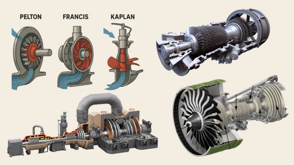
Figure 7: Schematic of axial flow compressor, Pelton, Francis, Kaplan hydraulic wheels, gas turbine and a steam turbine
Radial Flow Turbomachinery
In radial flow machines, the fluid enters the center of the spinning shaft and travels perpendicularly outward. This motion uses centrifugal force to throw the fluid away from the center. This specific geometric design is highly effective when an engineer needs a large pressure increase in a single physical step.
The spinning part in these machines is usually called an impeller. As the fluid leaves the spinning impeller, it enters a stationary spiral shell called a volute casing. The volute casing smoothly slows the fluid down, which forces the internal pressure to rise even higher. If you want to observe how the pressure distributes inside the volute and the impeller during operation, you can review our applied CFD for centrifugal pump analysis.
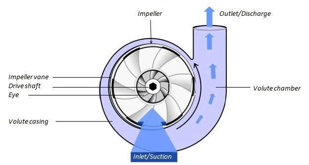
Figure 8: In radial flow turbomachinery, the impeller directs the fluid perpendicularly outward to generate a high-pressure rise.
Axial Flow Turbomachinery
Unlike the outward path of a radial machine, the fluid inside an axial flow turbine or an axial flow compressor travel in a straight line that is completely parallel to the central shaft. These machines produce smaller pressure changes than radial machines, but they can process much larger volumes of fluid in a very compact space.
For example, a modern aircraft engine relies on a large axial flow compressor to quickly pull in massive amounts of atmospheric air before fuel combustion. In open environments, a standard wind tower acts as an axial flow turbine to capture kinetic energy from the weather. You can study the aerodynamics of these large blades through CFD for wind turbine modeling. Similarly, ventilation and cooling systems use axial fans to displace air. Simulating these standard air movers requires specific setups, which you can learn about in our guide to the internal and external fan boundary condition in ANSYS Fluent.
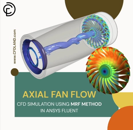
Figure 9: This is an example of axial flow in a fan simulation using ANSYS Fluent
Main Components of Turbomachinery
Turbomachinery consists of several key components that work together to enable efficient energy transfer between a fluid and a rotating shaft.
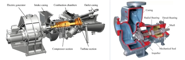
Figure 10: Key components of turbomachinery
Rotor (Impeller / Runner / Blades):
- The rotating part of the machine that interacts directly with the fluid.
- In pumps and compressors, the rotor imparts energy to the fluid.
- In turbines, the rotor extracts energy from the fluid.
- Common forms: Impeller (pumps), Rotor blades (turbines), Propeller (open flow)
Stator (Guide Vanes / Nozzles / Diffusers):
The stationary part that directs the flow into or out of the rotor.
- Helps control the velocity and pressure of the fluid.
- Improves efficiency and reduces turbulence.
- In turbines: often designed as nozzles to accelerate fluid before it hits the rotor.
- In compressors/pumps: used as diffusers to decelerate the flow and increase pressure.
Shaft:
- A mechanical component that transmits torque between the rotor and the driving or driven machine (e.g., motor or generator).
- Typically supported by bearings to ensure smooth rotation.
Casing (Housing):
- Encloses the internal components and contains the working fluid.
- In enclosed turbomachinery, the casing ensures pressure containment and directs the flow path.
- Also protects components and helps with heat dissipation or structural support.
Bearings and Seals:
- Bearings support the rotating shaft and reduce friction.
- Seals prevent leakage of the working fluid and protect against contamination.
Inlet and Outlet (Suction and Discharge Sections):
- These are the flow entry and exit points of the machine.
- Designed to minimize losses and ensure smooth transition of the fluid.
Diffuser / Volute (in Pumps and Compressors):
- A diffuser slows down the flow to increase pressure.
- A volute is a spiral-shaped casing that collects fluid from the impeller and converts velocity into pressure.
How Engineers Model the Rotating and Stationary Domains
Simulating these rotating machines is a major mathematical challenge for CFD engineers. The main challenge with these rotating machines is that the solid blades move at high speeds while the outer casing remains fixed. This means the computer model must calculate a rotating and stationary domain at the same time.
To solve this, we use specialized domain methods in ANSYS Fluent. For steady-state calculations, they use the moving reference frame (MRF) method. This approach keeps the mesh stationary but adds rotational forces mathematically to the fluid equations. For highly accurate, time-dependent studies, they use the sliding mesh method. In this setup, the rotor mesh actually rotates inside the stator mesh at every time step. To pass the physical fluid data accurately between these two different zones, the model requires a perfectly defined interface in CFD.
Another major factor is turbulence modeling in turbomachinery. As the fluid hits the fast-moving blades, it creates complex flow separation and high friction near the solid walls. By analyzing these flow patterns virtually, designers can predict the exact machine efficiency and prevent physical damage before building an expensive prototype.
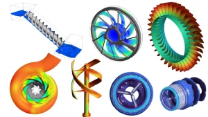
Figure 11: Engineers use moving reference frame (MRF) and sliding mesh methods to accurately simulate the rotating and stationary domains inside a turbomachine.
Conclusion
Turbomachinery is the foundation of global energy transfer. Whether it is an axial flow compressor inside a jet engine or a massive hydraulic turbine in a dam, all these machines rely on the same fundamental physics to convert energy between a flowing fluid and a rotating shaft. By understanding the velocity triangle, blade classification, and energy direction, engineers can design highly efficient systems for any industrial application.
Before you start setting up your own numerical models, it is highly recommended to review our main Turbomachinery CFD Simulation tutorials to see these physical laws in action. If you need professional engineering assistance for a dedicated turbomachinery project, our experts are ready to deliver highly accurate and optimized simulation results. Just leave a message on Whatsapp to discuss more.