
In aerospace engineering, designing flight vehicles that travel at high speeds requires a deep understanding of fluid mechanics. A canard missile is a specific type of flying vehicle that uses small wings near the front nose, known as canards, to steer accurately. These front wings allow the vehicle to change direction very quickly to track moving targets. However, calculating the exact air friction and lifting forces on these surfaces is highly complex. To design these vehicles safely, aerospace engineers perform a detailed Canard Missile CFD computer analysis. By conducting a highly accurate Canard Missile fluent simulation, designers can clearly observe the invisible air patterns flowing around the metal body. This numerical computer test measures the exact aerodynamic forces, such as drag and lift, before the physical object is manufactured in a factory. A complete CFD Analysis of Canard Missile allows engineers to find design problems, reduce air resistance, and improve flight stability. To achieve high accuracy, engineers must use proper computer grid methods and mathematical equations for compressible gases. To learn the exact computer skills necessary for solving high-speed airflows over flying vehicles, please explore our detailed Aerodynamics tutorials.
- Reference [1]: Sahu, Jubaraj. “CFD simulations of a finned projectile with microflaps for flow control.” International Journal of Aerospace Engineering1 (2017): 4012731.
- Reference [2]: Wee, Hong C. “Aerodynamic analysis of a canard missile configuration using ANSYS-CFX.” (2011).
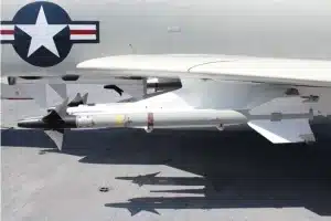
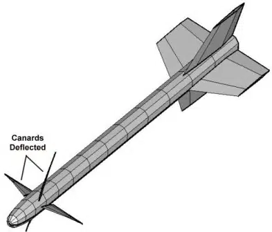
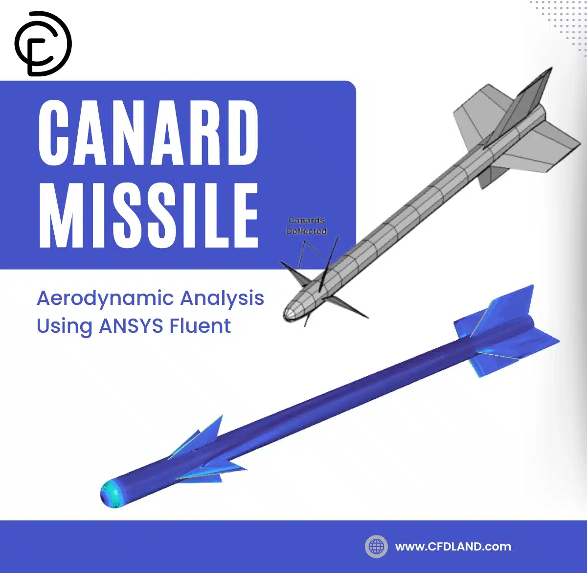
Figure 1: 3D geometric model of the canard missile, showing the nose cone, central body, forward canard surfaces, and rear tail fins.
Simulaiton Process: 3D Geometry and Advanced Poly-Hex Meshing
To begin this Canard Missile ANSYS Fluent project, we built a perfect 3D model inside the computer. The geometry carefully includes the sharp front nose, the main cylinder body, the forward steering canards, and the back tail fins. To mathematically measure the fast air, we used the Fluent Meshing tool to divide the empty sky into exactly 6,496,775 small 3D cells. We chose a special poly-hex mesh style for this test. Polyhedral shapes are much better than standard triangles because they fit perfectly around curved metal parts and save computer memory. We made the cells very thin and flat directly next to the missile skin to catch the exact friction forces. Inside the Canard Missile fluent software, we used the ideal-gas law (weakly compressible / low-speed regime) to copy real atmospheric air. We set the flying angle exactly at 4 degrees (Angle of Attack). This perfect setup allows the computer to calculate all the complex physics of straight and angled flight.
Figure 2: A close look at the 2D grid, showing the high-quality polyhedral cells and the very thin layers touching the metal wall.
Post-processing: Analysis of Aerodynamic Forces and Fluid Flow
To evaluate the flight performance of this vehicle, we must analyze the exact force data and the flow contours generated by the ANSYS Fluent. This scientific analysis explains exactly how the solid body interacts with the fast air. The post-processing data provides the primary aerodynamic force parameters. The software calculated the exact value for the lift coefficient (Cl) as 2.1613691. At the same time, the computer calculated the drag coefficient (Cd) as 0.85141414. These coefficients are non-dimensional numbers that represent the total upward pushing power and the total backward resistance of the vehicle. A lift coefficient of 2.16 is a very high number. It indicates that the missile is flying at a high angle of attack. At this steep angle, the bottom surfaces of the missile push heavily against the incoming air.
| Aerodynamic Parameter | Computer Variable Name | Exact Calculated Value |
| Lift Coefficient | (c_lift) | 2.1613691 |
| Drag Coefficient | (c_axial) | 0.85141414 |
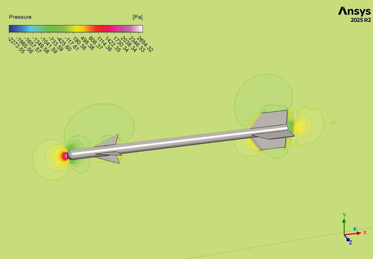
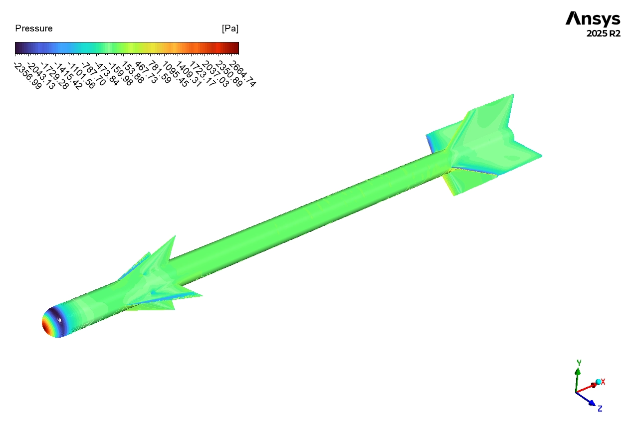
We can understand why these specific numbers happen by looking at the pressure contours. On the pressure map, the bottom surfaces of the front canards, the long cylindrical body, and the rear tail fins show bright red and orange colors. These colors represent very high static pressure. The fast air hits these bottom surfaces and slows down, which increases the local pressure. On the top surfaces of the missile, the computer displays blue colors, representing very low pressure. The high pressure on the bottom pushes the missile upward into the low-pressure zone on top. Because the entire long body and the wings all have this large pressure difference, the total upward force is very strong. This physical pressure difference directly explains why the computer calculated the high lift coefficient of 2.1613691.
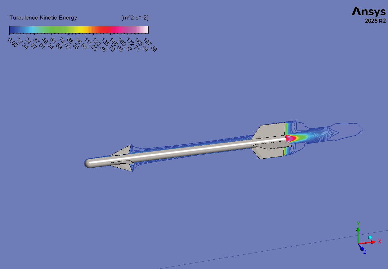
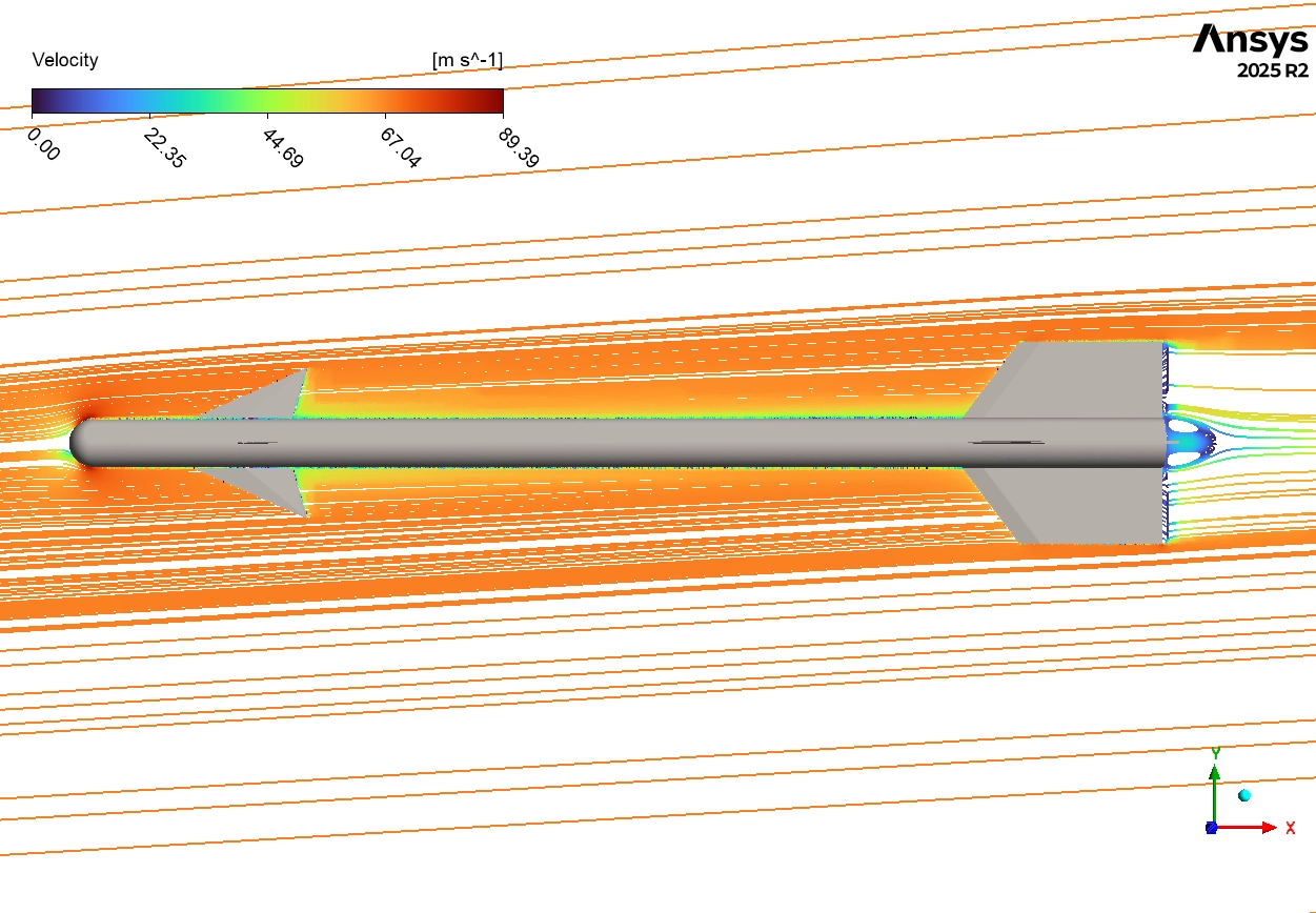
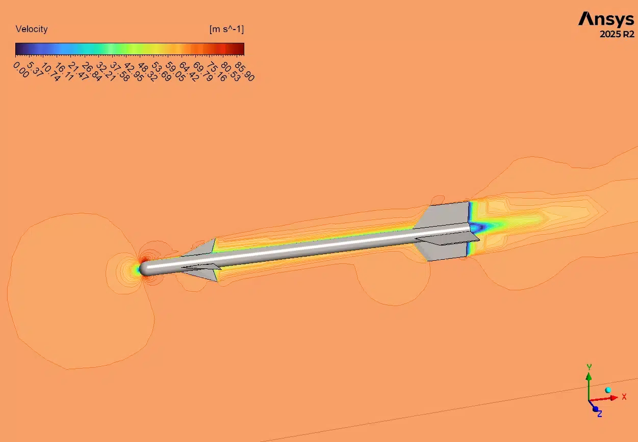
Next, we analyze the velocity contours and streamlines to understand the drag coefficient of 0.85141414. This drag number is substantial, meaning the missile engine must work hard to push through the air. When we look at the velocity picture, we see a dark blue zone exactly at the front tip of the nose. This is the stagnation point, where the air velocity drops to zero and pressure reaches its absolute maximum. Pushing this blunt nose through the air creates heavy form drag. Furthermore, the streamlines clearly reveal twisting, circular air patterns detaching from the tips of the front canards and rear wings. These are called tip vortices. They form because the high-pressure air below the wing naturally curls upward over the edge to reach the low-pressure air on top. Creating these spinning vortices consumes a lot of mechanical energy, which pulls the missile backward. Engineers call this induced drag. The combination of the heavy pressure on the nose and the strong tip vortices at this high angle of attack perfectly explains the total drag coefficient of 0.851.
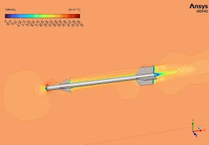
Figure 3: Velocity contour from ANSYS Fluent canard missile, visualizing the different speeds of air around the body and the slow air hiding behind the fins.
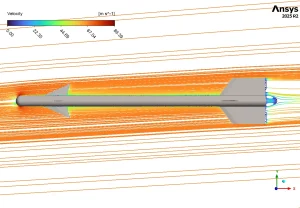
Figure 4: Velocity streamlines from ANSYS Fluent CFD showing, illustrating the twisting circular air paths (vortices) leaving the tips of the lifting wings.

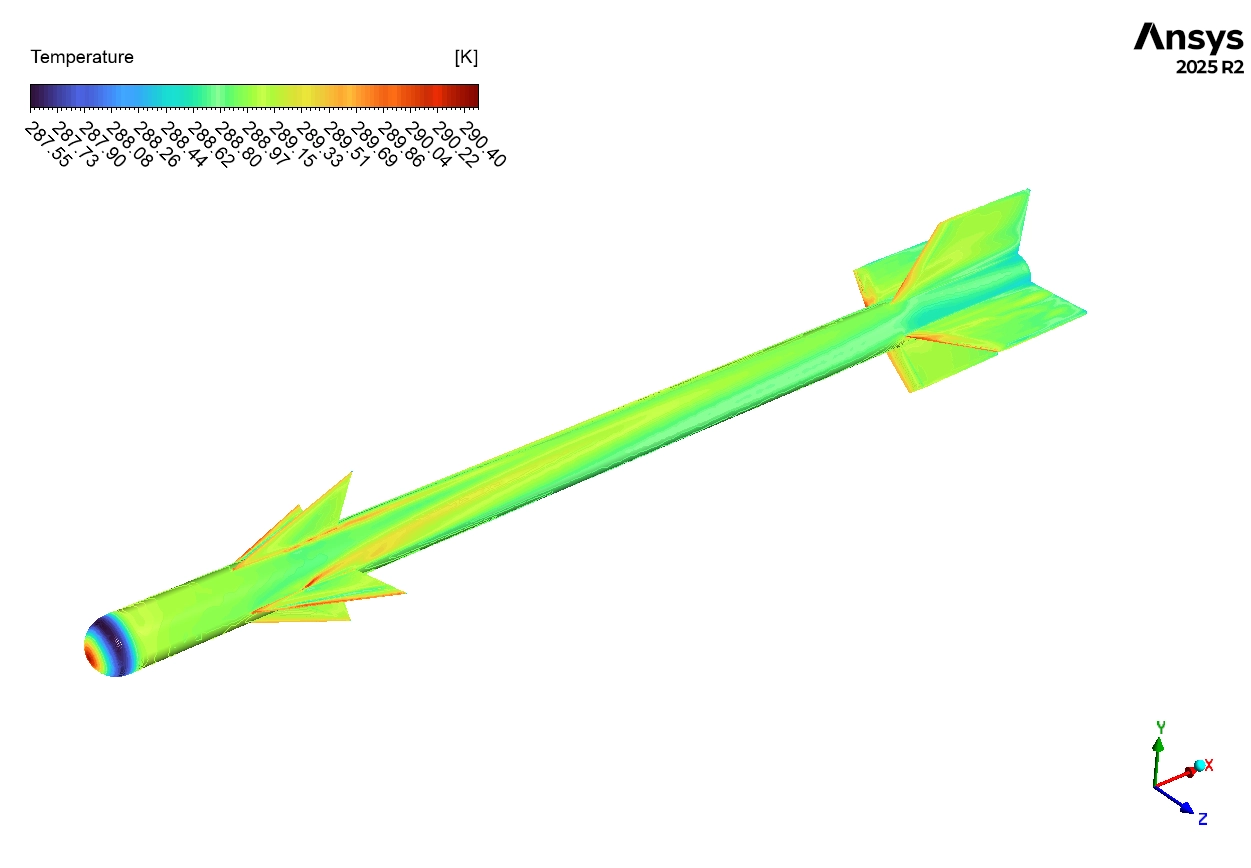
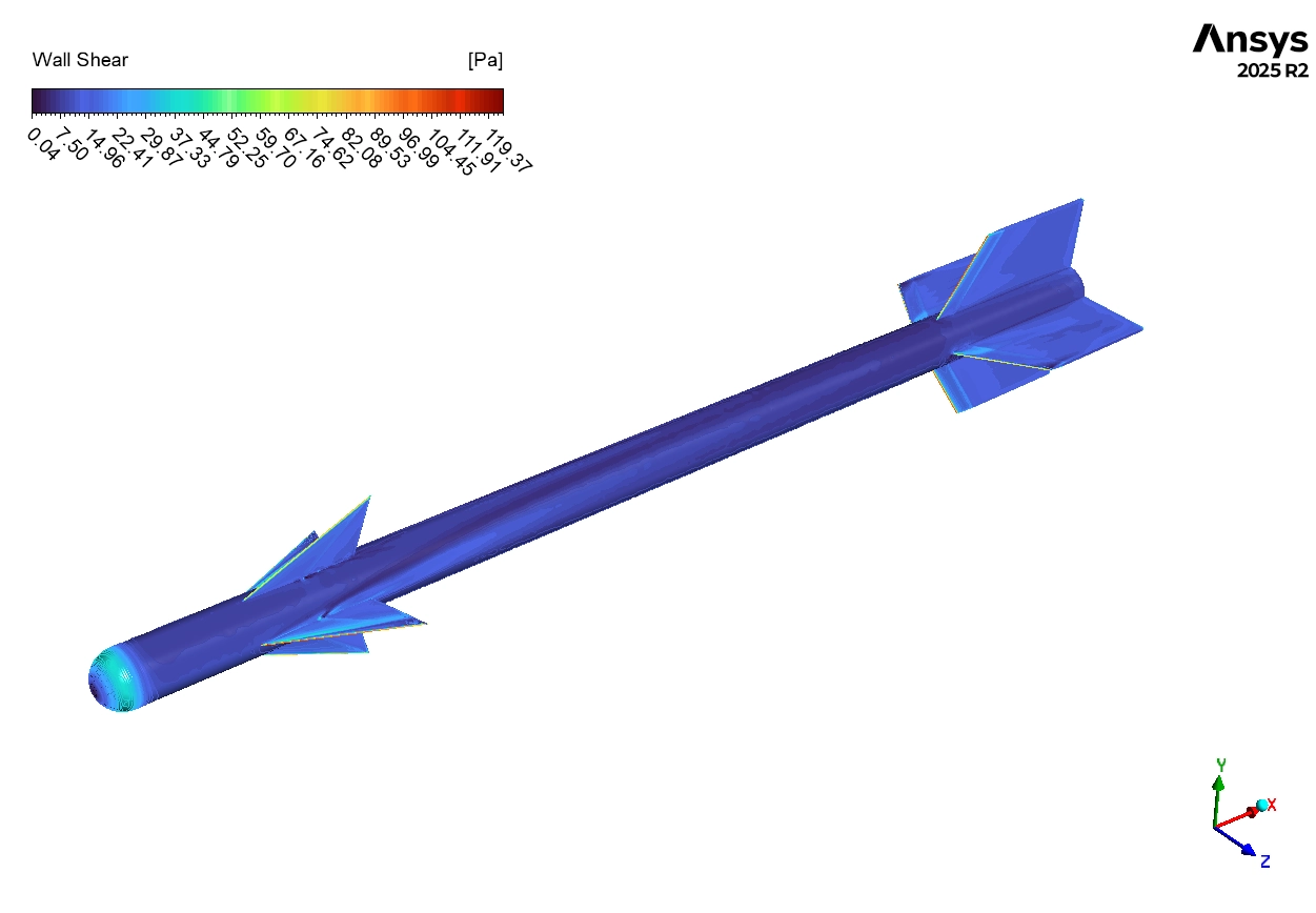
Figure 5: Wall shear stress contour, showing the friction forces rubbing against the solid metal skin of the flying missile.
Finally, we study the wall shear stress contour to locate regions of high skin friction. As the missile travels forward, the air rubs violently against the solid metal. The contour shows distinct red and orange zones directly on the sharp leading edges of the forward canards and the rear tail fins. These sharp edges cut through the stationary air, creating very high local friction forces. This skin friction adds an extra layer of resistance to the total drag. By understanding these exact fluid events—the high-pressure lifting zones, the energy-draining tip vortices, and the friction on the sharp edges—aerospace engineers can confidently modify the canard design to improve stability and speed.
Frequently Asked Questions (FAQ)
- Why are canards used on modern missiles?
- Canards are small wings placed near the front of the missile. They are used to improve maneuverability. They allow the missile to change its pitch quickly and steer accurately toward moving targets at high speeds.
- What creates the high lift coefficient of 2.16 in this simulation?
- The high lift is created because the missile is flying at an angle of attack. The incoming air hits the bottom of the canards, the main body, and the tail fins, creating a large high-pressure zone that pushes the vehicle upward.
- What are tip vortices and how do they affect aerodynamic drag?
- Tip vortices are spinning circles of air that roll off the tips of the wings. They happen when high-pressure air from the bottom escapes to the top. Creating these spinning circles wastes energy, which pulls the missile backward. This increases the total drag coefficient.


Reviews
There are no reviews yet.