

In the fluid engineering industry, cavitation is a highly destructive physical problem. When liquid flows very quickly through a tight space, the local pressure drops drastically. If this pressure falls below the natural vapor pressure of the liquid, the water instantly boils without any heat. This creates thousands of vapor bubbles. When these bubbles travel to high-pressure areas, they collapse violently. This violent collapse creates severe shockwaves, loud aeroacoustics noise, and destroys solid metal pipes. To prevent this equipment failure, engineers study the Geometric Design Effect on Cavitation CFD. By changing the shape of the pipe, engineers can smoothly control the liquid pressure and stop bubbles from forming.Performing a CFD Analysis of Geometric Design Effect on Cavitation helps designers see exactly where the pressure drops dangerously low. Inside a Geometric Design Effect on Cavitation fluent simulation, engineers test different corner shapes to measure the exact vapor volume fraction. Calculating this phase change requires a strong understanding of multiphase physics and mass transfer equations. To deeply learn how liquids turn into vapor inside computational environments, please carefully explore our comprehensive Mass Transfer tutorials.
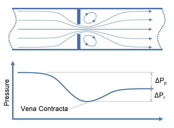
Figure 1: Schematic of Orifice Pressure Drop – A structural diagram illustrating how fluid accelerates through a restricted orifice, causing the pressure to plunge rapidly at the throat section.
Simulation Process: Cavitation setup in Fluent
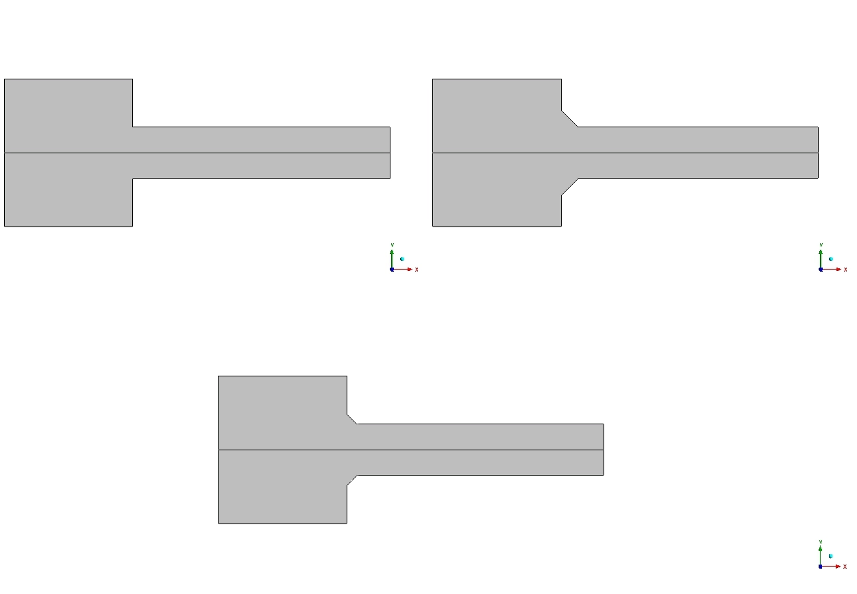
To properly evaluate this Geometric Design Effect on Cavitation ANSYS Fluent project, we built a 2D axisymmetric computational representation of a standard pipe orifice. To learn how shape optimization for cavitation works, we created three different geometric cases for a direct comparison. Case 1 features a basic, sharp 90° inlet corner. Case 2 features a smooth 3.5 mm radius chamfer. Case 3 features a slightly smaller 2.5 mm radius chamfer. We used an exceptionally fine mesh in the throat region to accurately capture the high-velocity fluid movements.
We activated the Mixture multiphase model to track both liquid water and water vapor at the same time. Next, we activated the cavitation mathematical model. We set the critical vapor pressure limit to exactly 3540 Pa. This means if the fluid pressure drops below 3540 Pa, the software will automatically calculate the formation of cavitation bubbles.
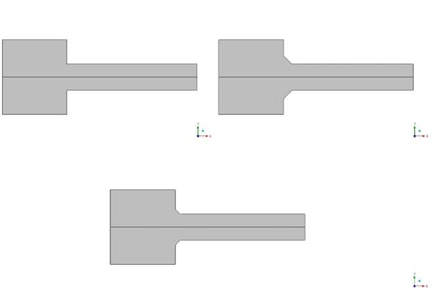
Figure 2: Three Evaluated Geometric Models – The computational representation comparing the sharp 90° baseline corner against the optimized 3.5 mm and 2.5 mm rounded chamfer configurations.
Post-processing: Analysis of Pressure Drops and Vapor Fractions
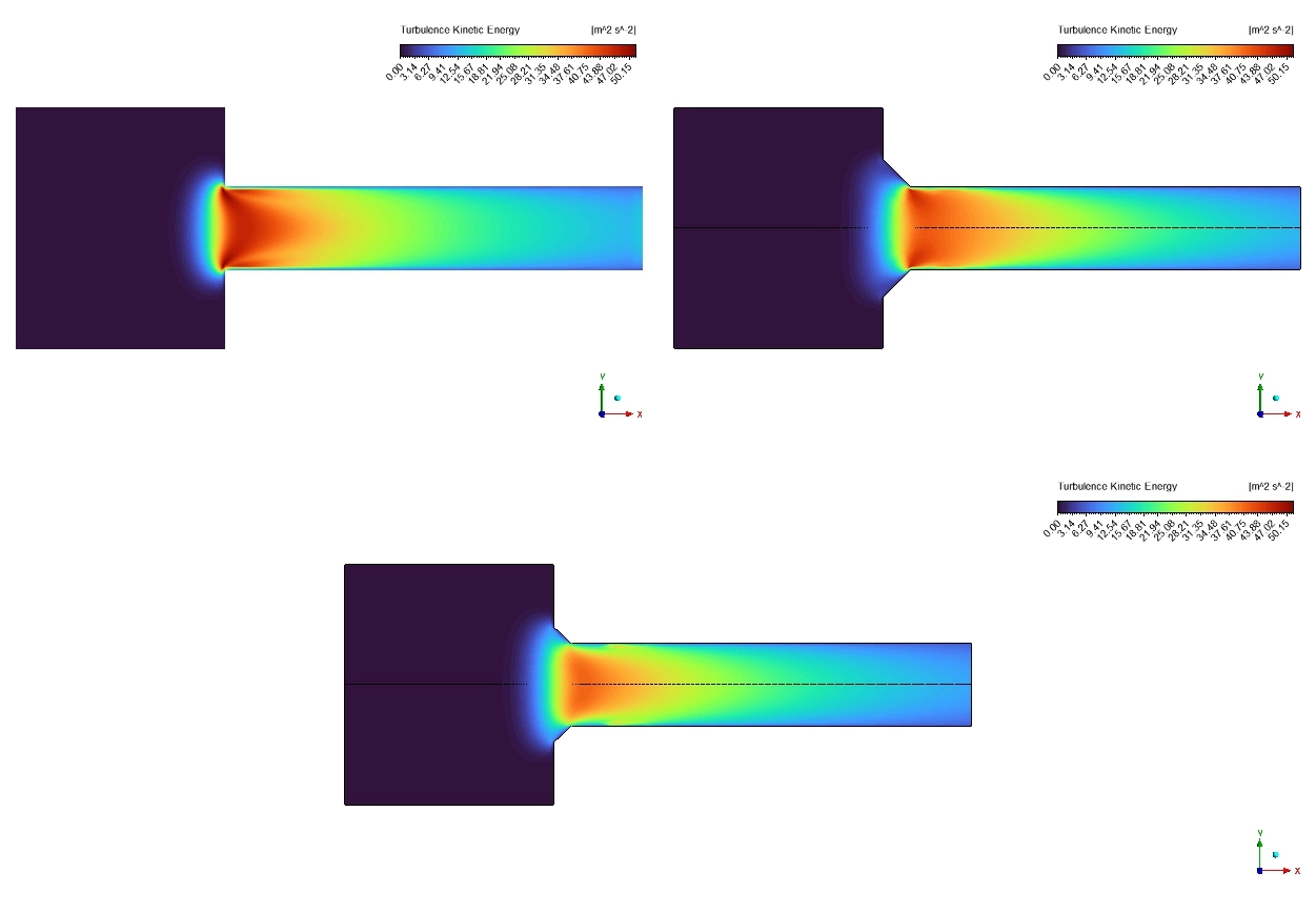
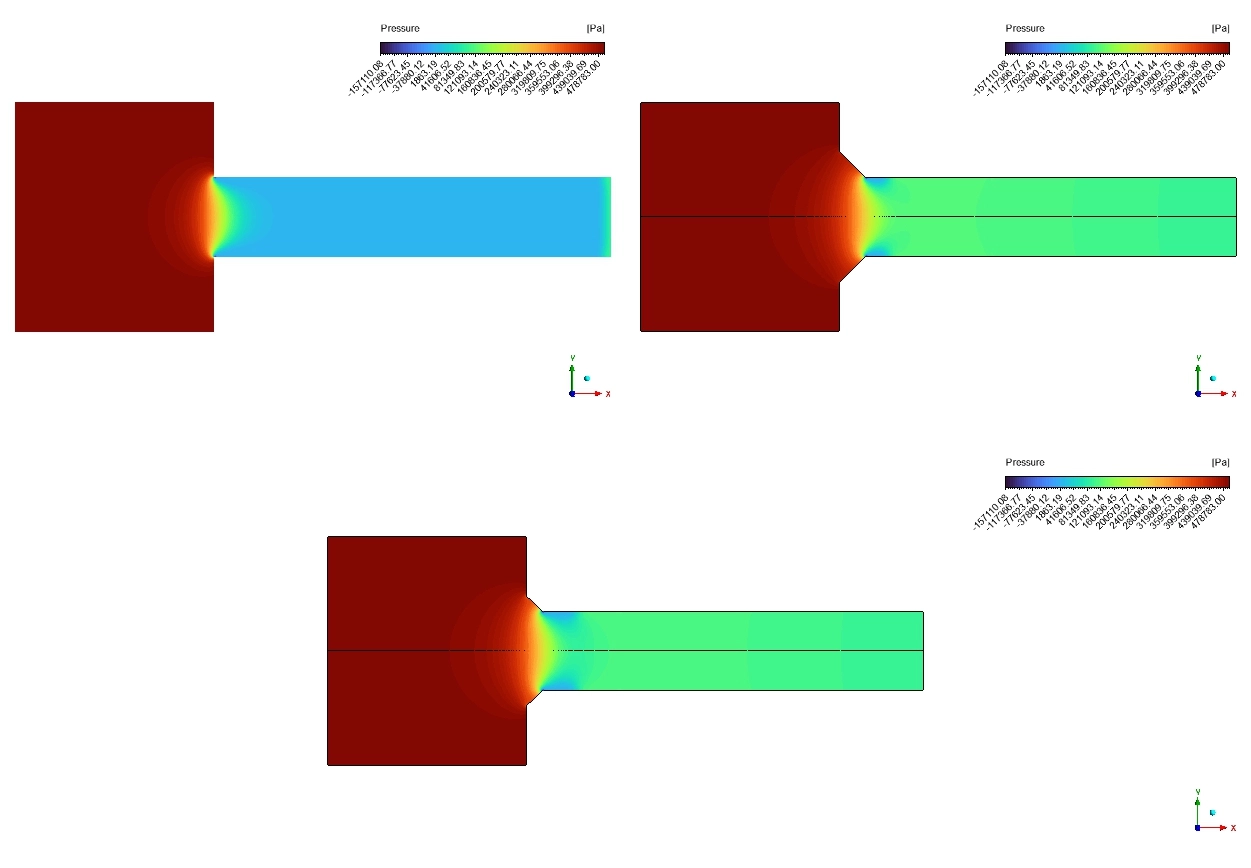
Let us carefully analyze the post-processing results to understand the true engineering success of these geometric changes. We must read the pressure contours and the vapor fraction graphs together to see exactly how the shape controls the fluid. We begin by looking at the pressure distribution. In Case 1 (the sharp 90° corner), the liquid hits the sharp edge and suddenly separates from the wall. This sudden separation causes a massive, dangerous pressure drop. The pressure plunges from 100,000 Pa down to an extreme low of 3,000 Pa. Because 3,000 Pa is strictly below our 3540 Pa limit, the water rapidly boils. However, when we look at the chamfered designs (Case 2 and Case 3), the physics change entirely. The curved chamfers guide the water smoothly. The pressure transitions gently and stays safely between 20,000 Pa and 30,000 Pa in the throat. Because the pressure never drops below the critical limit, bubble formation is completely physically prevented.
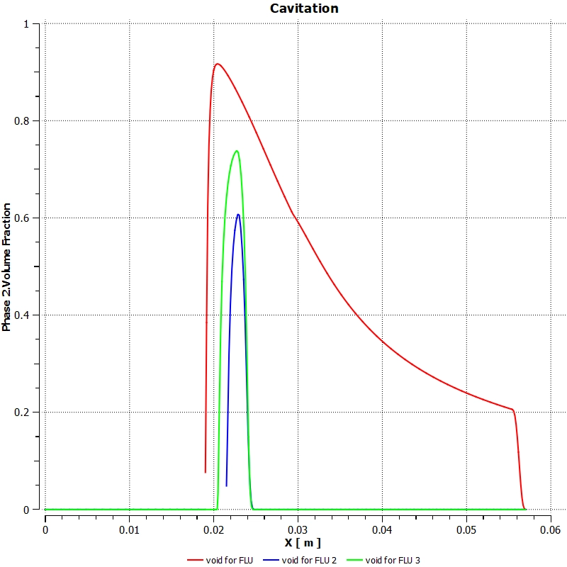
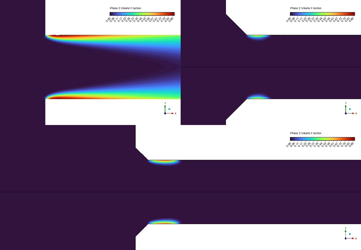
Next, we evaluate the exact severity of the bubbles using the Phase 2 Volume Fraction contours. For the sharp baseline Case 1, the software reveals a massive cavitation cloud stretching 43 mm down the pipe. The average vapor volume fraction is calculated at 0.036231 (3.62%), with localized peak zones reaching a severe 92% vapor concentration. This indicates terrible flow blockage and severe metal erosion risk.
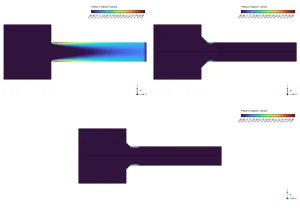
Figure 3: Phase 2 Vapor Volume Fraction Contours – A visual comparison proving that the sharp corner (Case 1) generates a massive vapor cloud, while the chamfered edges (Cases 2 and 3) remain almost completely free of vapor.
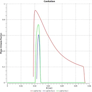
Figure 4: Wall Surface Vapor Fraction – An erosion risk map showing high concentrations of dangerous vapor bubbles collapsing directly against the solid metal walls in the baseline design.
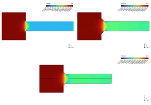
Figure 5: Static Pressure Distribution Contours – A fluid physics visualization demonstrating how the sharp edge creates a dangerous low-pressure zone below 3540 Pa, while rounded edges maintain safe, stable pressures.
In sharp contrast, the cavitation fluent results for the optimized shapes are incredible. For Case 2 (3.5 mm chamfer), the average vapor fraction drops to 1.23 × 10⁻²⁷. For Case 3 (2.5 mm chamfer), it drops to 2.84 × 10⁻²⁸. In engineering mathematics, these microscopic numbers mean the vapor is essentially zero. The cavitation cloud length shrinks from 43 mm down to just 8 mm before instantly collapsing. This geometric optimization successfully delivers a 99.999% reduction in cavitation. This exact numerical data mathematically proves that simply rounding a sharp corner perfectly suppresses sudden pressure drops, making this geometric design highly superior for extending the lifespan of hydraulic machinery.
Table 1: Quantitative Cavitation Reduction Analysis
| Geometric Design Case | Inlet Configuration | Average Vapor Volume Fraction |
| FLU Case 1 (Basic) | Sharp 90° corner | 0.036231 (3.62%) |
| FLU Case 2 | 3.5 mm radius chamfer | 1.23 × 10⁻²⁷ |
| FLU Case 3 | 2.5 mm radius chamfer | 2.84 × 10⁻²⁸ |
Frequently Asked Questions (FAQ)
- What is the Geometric Design Effect on Cavitation?
- A: It is the science of changing the physical shape of a pipe or valve (like adding a curved chamfer) to smoothly guide the liquid. Smooth shapes stop the fluid pressure from dropping too low, which perfectly prevents dangerous vapor bubbles from forming.
- Why does the sharp 90° corner cause cavitation?
- A: A sharp corner forces the fast-moving water to violently detach from the metal wall. This creates a highly localized vacuum where the pressure drops below the water’s natural vapor pressure (3540 Pa), causing the water to boil instantly.
- How successful was the shape optimization in this simulation?
- A: By adding a simple 2.5 mm or 3.5 mm radius chamfer, the ANSYS Fluent software calculated a massive 99.999% reduction in vapor volume. This proves that minor geometric changes can completely save industrial pipes from erosion damage.


Reviews
There are no reviews yet.