
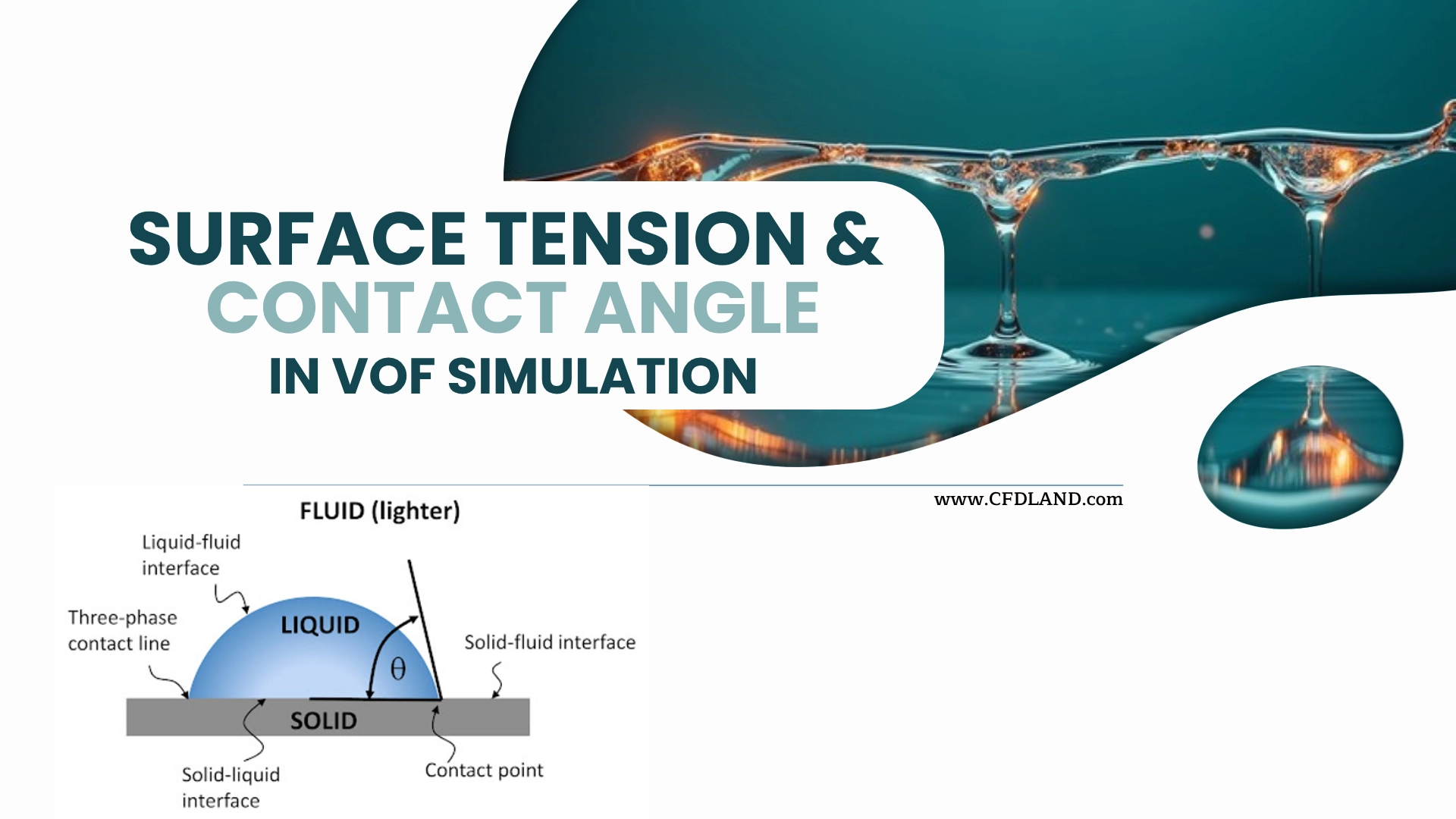
VOF Simulation is one of the main methods for ANSYS Fluent Multiphase flow. It is used when two fluids have a clear interface. This interface can be between water and air, oil and water, or another two-phase system. In this method, ANSYS Fluent VOF tracks the position and shape of the interface with the volume fraction field. Surface Tension Modeling is very important in this type of model. Surface tension controls the force at the Liquid-Gas Interface or liquid-liquid interface. This force can change the shape of a droplet, bubble, or free surface. So, correct CFD Surface Tension setup is needed for stable and real results. Contact Angle CFD is also important when the interface touches a solid wall. The contact angle shows how much one phase wets the wall. In Wall Adhesion in ANSYS Fluent, this angle is used to define the wetting behavior near the wall. It helps Fluent calculate the near-wall shape of the interface.
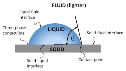
Figure 1: Droplet (Liquid) on a wall (Solid) with contact angle. This image shows how Contact Angle CFD defines hydrophilic or hydrophobic behavior in ANSYS Fluent VOF.
Hydrophilic and hydrophobic behavior are also linked to this contact angle. If the second phase spreads on the wall, the wall acts more hydrophilic for that phase. If the second phase does not spread on the wall, the wall acts more hydrophobic for that phase. This is why the contact angle must be set with care in Contact angle setup in ANSYS Fluent VOF. The main idea is simple: surface tension controls the interface shape, and contact angle controls how the interface touches the wall. These two settings are key parts of any VOF surface tension modeling guide. They are also very important in droplet motion, micro droplet generation, capillary flow, and free surface flow.
💡 Note for Beginners: Do you want to learn the basic theory of VOF first? Read our complete guide: Comprehensive Guide on Volume of Fluid (VOF) Model in Multiphase CFD Simulation. This guide explains the basic equations, phases, and settings of the VOF Simulation method in ANSYS Fluent.
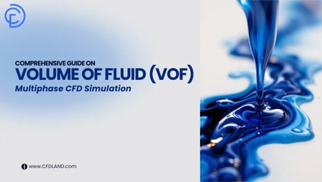
Figure 2: complete guide VOF method in ANSYS Fluent.
Basic Theory of Surface Tension and Contact Angle in VOF
In a VOF Simulation, two or more fluids share one flow domain. For example, water and air can move in the same channel. ANSYS Fluent VOF does not track each small fluid particle. It tracks how much of each cell is filled by each phase. This is done with the Volume Fraction Equation. So, each cell can be full of water, full of air, or a mix near the interface.
The boundary between two phases is called the Liquid-Gas Interface. This interface has a special force. This force is called surface tension. In real flow, surface tension tries to keep the interface smooth and small. It is very important in droplets, bubbles, jets, microchannels, and Free Surface Flow Simulation. So, correct Surface Tension Modeling is needed when the shape of the interface is important.
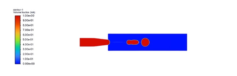
Figure 3: Volume fraction contour in a VOF Simulation. The interface shape depends on Surface Tension Modeling and the Surface Tension Coefficient in ANSYS Fluent Multiphase.
In ANSYS Fluent Multiphase, surface tension is often modeled with the CSF Model. CSF means Continuum Surface Force Model. This model changes the surface tension effect into a body force near the interface. This helps Fluent calculate the force inside the cells. For this reason, the CSF Model is one of the main parts of CFD Surface Tension analysis.
The user must also define the Surface Tension Coefficient. This value depends on the two phases. For example, the surface tension between water and air is not the same as the surface tension between oil and water. If this value is wrong, the droplet shape, breakup time, and interface motion can also be wrong. So, How to define surface tension coefficient in Fluent is an important part of any VOF surface tension modeling guide.
The Surface Tension Coefficient controls the strength of the force at the interface between two phases.
Contact angle is another key part of this physics. The contact angle is the angle between the wall and the interface at the contact line. It shows how one phase wets the solid wall. In Contact Angle CFD, this angle helps Fluent define the near-wall interface shape. This is very important when the interface touches a wall, such as in a microchannel, a droplet on a plate, or a T-junction.
In Fluent, this behavior is linked to Wall Adhesion in ANSYS Fluent. The user sets the angle in the Wall Adhesion Boundary Condition. This setting tells Fluent how the selected phase should meet the wall. So, Wall adhesion setup in ANSYS Fluent is not only a visual setting. It changes the local force balance near the wall.

Figure 4: Contact angle and wall wetting behavior. A low contact angle shows hydrophilic behavior. A high contact angle shows hydrophobic behavior in Contact Angle CFD.
Hydrophilic and hydrophobic behavior must be read with care. If the contact angle is less than 90°, the liquid spreads more on the wall. This is hydrophilic behavior. If the contact angle is more than 90°, the liquid spreads less on the wall. This is hydrophobic behavior. If the angle is very high, the surface can be called super-hydrophobic.
The meaning of the angle depends on the phase that touches the wall. In Contact angle setup in ANSYS Fluent VOF, the user must know which phase is the wetting phase. For example, if water is the second phase, the contact angle can show if water wets the wall or avoids the wall. This point is very important in Wetting Behavior Simulation.
Table 1: Contact Angle
| Contact Angle | Wall Behavior | Simple Meaning in Fluent |
| θ < 90° | Hydrophilic | The phase spreads on the wall. |
| θ = 90° | Neutral | The phase has medium wetting. |
| θ > 90° | Hydrophobic | The phase does not spread easily. |
| θ > 150° | Super-hydrophobic | The phase strongly avoids the wall. |
These forces are also linked to Capillary Effects in CFD. Capillary effects are strong when the flow is small, the channel is narrow, or the droplet is tiny. This is common in microfluidic devices. In these cases, surface tension and contact angle can be as important as pressure and velocity. This is why many users search for How to simulate capillary effects in ANSYS Fluent.
For a stable model, the physics and the numeri’s must match. The mesh must be fine near the interface. The time step must be small enough. The wall angle must match the real surface. If not, the model may show a wrong droplet shape, false wall wetting, or unstable interface motion. These points are also part of the Best practices for VOF simulation in Fluent. In VOF, surface tension controls the interface force, and contact angle controls the wall wetting shape. Both must be correct for a reliable ANSYS Fluent Multiphase result.
Geometry, Phases, and Physical Model
Before the Fluent VOF Setup, the user must prepare the physical model. This step is very important. A good VOF Simulation starts with a clear geometry, correct phases, clear wall zones, and good boundary names. If these items are not clear, the setup in ANSYS Fluent Multiphase can become hard and wrong.
The geometry depends on the problem. It can be a simple tank, a pipe, a microchannel, a droplet on a wall, or a T-junction. In this article, one important example is Microdroplet Generation CFD Analysis: VOF Simulation in a T-Junction using ANSYS Fluent. In this model, two fluids enter a small channel from different inlets. One phase is continuous. The other phase is dispersed. The dispersed phase forms small droplets because of flow force and Surface Tension Modeling.

Figure 5: T-junction geometry for microdroplet generation. This model is useful for studying VOF Simulation, Surface Tension Modeling, and Contact Angle CFD in ANSYS Fluent.
In each ANSYS Fluent VOF model, the phases must be defined with care. One phase is usually the primary phase. The other phase is the secondary phase. For example, air can be the primary phase and water can be the secondary phase. In another case, oil can be the primary phase and water can be the secondary phase. The user must define density, viscosity, and the Surface Tension Coefficient for the phase pair.
The interface is the region where the two phases meet. In VOF Simulation, Fluent finds this region with the Volume Fraction Equation. A volume fraction value of 1 means that the cell is full of one phase. A value of 0 means that the cell has none of that phase. A value between 0 and 1 means that the cell is near the interface. This is why Interface Tracking Method is a key part of Free Surface Flow Simulation.
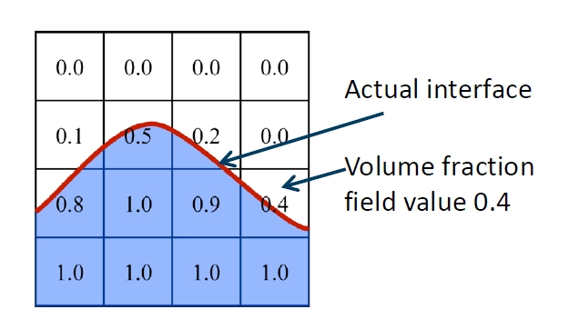
Figure 6: Volume fraction in a VOF Simulation. Fluent uses the Volume Fraction Equation to show the liquid, gas, and Liquid-Gas Interface in each cell.
The boundary zones must also be named correctly. The model can include velocity inlets, pressure outlets, walls, and symmetry planes. In a T-junction case, the main channel inlet can be used for the continuous phase. The side channel inlet can be used for the dispersed phase. The outlet is usually a pressure outlet. The channel walls are used to set Wall Adhesion in ANSYS Fluent and the contact angle.
Correct boundary names help the user set phase flow, wall adhesion, and contact angle without mistakes in Fluent.
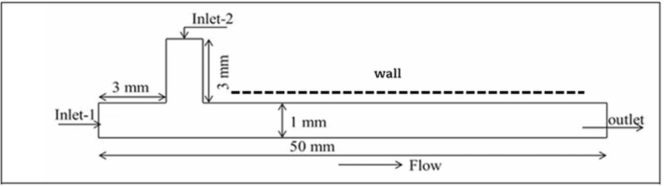
Figure 7: Boundary zones in a T-junction VOF model. Clear zone names help define velocity inlet, pressure outlet, wall adhesion, and contact angle setup in ANSYS Fluent VOF.
The wall condition is very important when the interface touches the wall. The wall can act as hydrophilic or hydrophobic for the selected phase. This behavior is controlled by the contact angle. A low contact angle means more wetting. A high contact angle means less wetting. So, in Contact angle setup in ANSYS Fluent VOF, the user must know which phase is the wetting phase and which wall material is used.
Gravity may also be needed in some models. For a large tank or free surface flow, gravity can strongly change the interface shape. For a microchannel or small droplet, surface tension can be stronger than gravity. So, the user must check the length scale of the model. This is important for Capillary Effects in CFD. In small channels, surface tension and contact angle can control the full flow pattern.
Most VOF Simulation cases with droplets and interface motion should be transient. A steady model cannot show the real change of the interface with time. It cannot show droplet stretching, neck formation, pinch-off, wall wetting, or droplet motion well. These events happen step by step. So, they need a time-dependent calculation.
In a transient ANSYS Fluent VOF model, the interface between two phases moves and changes shape. For example, a droplet can move on a wall. During motion, the droplet can stretch. The front side of the droplet can advance, and the back side can recede. Because of this, the contact angle near the wall can change with time.
This behavior depends on the correct Surface Tension Coefficient and Wall Adhesion Boundary Condition. The surface tension controls the force at the interface. The contact angle controls how the phase wets the wall. If these values are wrong, the droplet shape and wall wetting will also be wrong.
In transient VOF simulation, the interface shape and contact angle can change with time. Correct surface tension and contact angle settings are needed for real droplet motion.
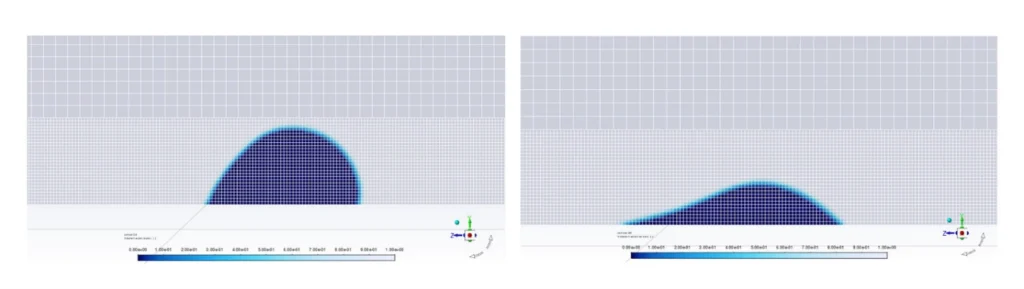
Figure 8: Transient VOF simulation of a droplet moving on a wall. The droplet stretches with time, and the contact angle changes at the wall. Correct Surface Tension Coefficient and Wall Adhesion settings help ANSYS Fluent predict the interface shape.
The initial condition must also be clear. At the start of the simulation, the domain can be filled with the primary phase. Then the secondary phase can enter from an inlet. In other cases, the user can patch a region with the secondary phase. For example, the user can patch an initial droplet shape near a wall. This means Fluent starts with a known volume fraction field.
A correct initial field helps the solution become stable faster. It also helps the Volume Fraction Equation track the interface better from the first time step. This is very important for Surface Tension Modeling, Contact Angle CFD, and Wetting Behavior Simulation.
Fluent Tab: VOF Model, Material Properties, Surface Tension, and Wall Adhesion Settings
In this section, we review the main ANSYS Fluent VOF windows. These settings are very important for modeling a drop on a wall. The user must set the VOF Model, fluid properties, Surface Tension Coefficient, and Wall Adhesion Boundary Condition correctly. In a drop-on-wall simulation, the liquid drop touches a solid wall. The drop shape depends on surface tension and contact angle. The wall can be hydrophilic or hydrophobic. So, the contact angle setup is very important. In Fluent VOF, the most important settings for a drop on a wall are VOF model, material properties, surface tension, and wall adhesion contact angle.
ANSYS Fluent VOF Model Settings Window
The first step is to enable the VOF Model in Fluent. In this window, select Volume of Fluid (VOF). The VOF Simulation method is used when the interface between two phases is clear. It is useful for a liquid drop in air, droplet motion, free surface flow, bubbles, and wall wetting.
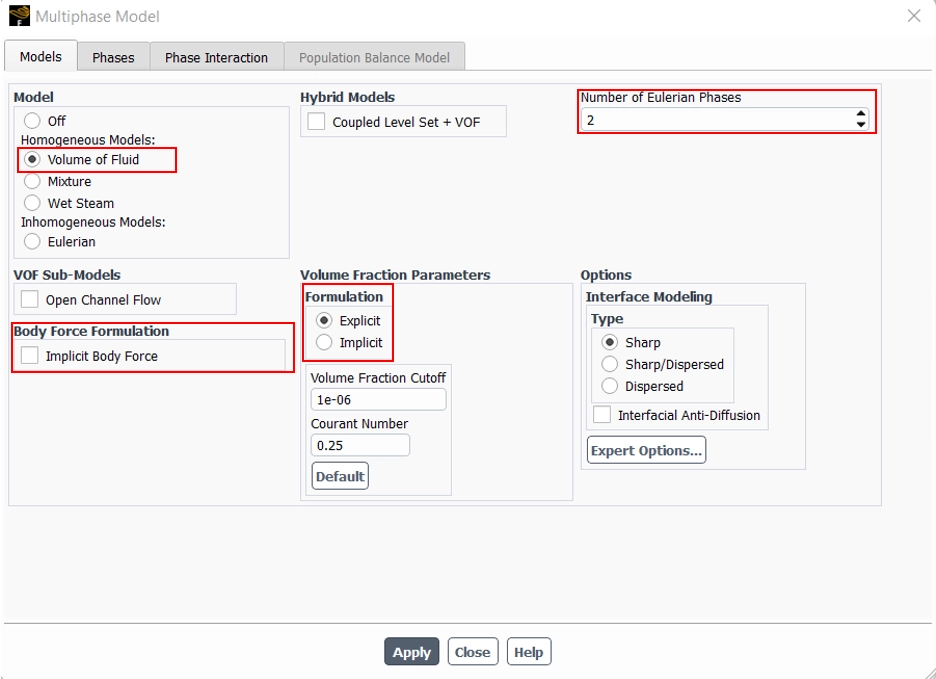
Figure 9: ANSYS Fluent VOF Model Settings Window. In this window, the user enables the VOF model to track the interface between the liquid drop and the surrounding phase.
In a simple drop-on-wall case, the number of phases is usually two. For example, one phase is air and the other phase is water. Fluent tracks the interface between these two phases.
The user can also choose the volume fraction formulation. The implicit option is more stable. The explicit option can give a sharper interface, but it needs a smaller time step.
Table 2: VOF Window Option
| VOF Window Option | Simple Meaning | Why It Is Important |
| VOF Model | Activates Volume of Fluid method | It tracks the drop interface. |
| Number of Phases | Defines the fluids | It is needed for air-water or oil-water cases. |
| Volume Fraction Formulation | Sets implicit or explicit VOF | It affects stability and interface sharpness. |
| Implicit Body Force | Helps with gravity | It improves stability when gravity is important. |
The VOF Model Settings Window tells Fluent how to track the interface between the liquid drop and the second phase.
ANSYS Fluent Properties Definition Window
After the VOF model is active, the user must define the fluid properties. In this window, define density and dynamic viscosity for each phase. These values affect the drop shape, drop motion, spreading, and wall wetting.
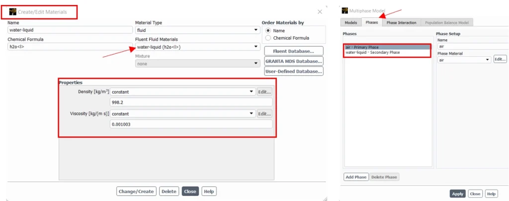
Figure 10: ANSYS Fluent Properties Definition Window. Density and viscosity must be defined for each phase in a drop-on-wall VOF simulation.
For example, in a water-air case, air can be the primary phase and water can be the secondary phase. The user must assign the correct material to each phase.
The material data must match the real fluids and the real temperature. If density or viscosity is wrong, the drop shape and motion can be wrong.
Correct material properties are needed before surface tension and contact angle can give reliable results.
ANSYS Fluent Surface Tension Coefficient Definition Window
The next step is to define the Surface Tension Coefficient. This value controls the force at the interface between two phases.
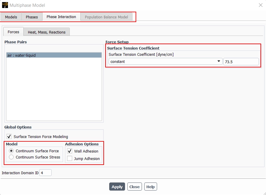
Figure 11: ANSYS Fluent Surface Tension Coefficient Definition Window. The surface tension coefficient defines the interface force between the drop and the surrounding phase.
Surface tension tries to keep the drop rounded. In Fluent, this effect is usually calculated with the CSF Model, or Continuum Surface Force Model. This model applies surface tension force near the interface cells.
The unit of surface tension is usually N/m. For example, water-air surface tension at room temperature is about 0.072 N/m.
In a drop-on-wall simulation, surface tension controls how round or flat the drop becomes. A high surface tension keeps the drop more rounded. A low surface tension lets the drop spread more easily.
The Surface Tension Coefficient controls the strength of the interface force and directly affects the drop shape.
Boundary Conditions: ANSYS Fluent Wall Adhesion Boundary Condition
The Wall Adhesion Boundary Condition is used when the drop touches a solid wall. This setting defines the contact angle. In some Fluent versions, wall adhesion must first be enabled in the multiphase settings. Then the contact angle field appears in the wall boundary condition panel.
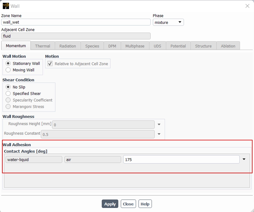
Figure 12. ANSYS Fluent Wall Adhesion Boundary Condition. The contact angle defines hydrophilic or hydrophobic wall behavior for a drop on a wall.
The contact angle is entered in degrees. It shows how the liquid drop wets the wall(Table 1: Contact Angle).
This setting must be used carefully. The user must know which phase the contact angle refers to. For example, if water is the liquid phase, the contact angle shows how water wets the wall.
In a drop-on-wall model, a small contact angle makes the drop spread. A large contact angle makes the drop bead up. So, this setting is very important for Contact Angle CFD and Wetting Behavior Simulation.
In ANSYS Fluent, the contact angle is the main input for hydrophilic and hydrophobic wall behavior in VOF simulations.
Geometry and Mesh Setup for VOF Simulation
A good VOF Simulation starts with a clean geometry. The flow domain must show the real path of each phase. It must also show the wall, inlet, outlet, and interface region clearly. This is very important in ANSYS Fluent Multiphase, because the Volume Fraction Equation needs a correct domain to track the phases.
The geometry should not have very small extra edges or bad gaps. These parts can make the mesh weak. They can also make the Liquid-Gas Interface unstable. For droplet flow, jet flow, microchannel flow, and Free Surface Flow Simulation, the interface path must be clear before the mesh step.
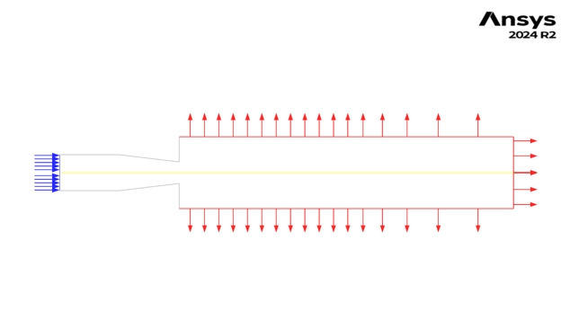
Figure 13: Clean geometry for ANSYS Fluent VOF. Clear inlets, outlets, walls, and interface path help improve VOF Simulation accuracy.
The mesh must be fine where the interface moves. This is the most important rule in ANSYS Fluent VOF. A coarse mesh can make the interface thick and unclear. It can also give a wrong droplet shape, wrong breakup time, or wrong wall wetting. So, the mesh near the interface, wall, contact line, and small flow gaps must be refined.
Mesh near the wall is very important for Contact Angle CFD. The contact angle is used in the Wall Adhesion Boundary Condition. If the wall mesh is poor, Fluent cannot show the correct hydrophilic or hydrophobic behavior. This can cause a wrong Wetting Behavior Simulation.
Surface tension also needs a good mesh. In Surface Tension Modeling, Fluent uses the CSF Model, or Continuum Surface Force Model, to apply force near the interface. If the mesh is not good, the CFD Surface Tension force can become noisy. This may create false small velocities near the interface. These false velocities are called spurious currents.
For a stable VOF model, the mesh must be fine near the interface and near the wall contact line.
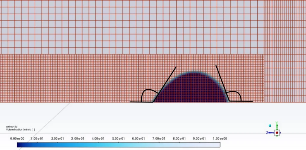
Figure 14: Fine mesh near the interface and wall. This helps Contact Angle CFD, Surface Tension Modeling, and Wall Adhesion in ANSYS Fluent.
The time step must also match the mesh size. A very fine mesh with a large time step can make the solution unstable. This is common in Capillary Effects in CFD, because surface tension can move the interface fast in small zones. A smaller time step helps Fluent track the interface better.
The table below shows the main geometry and mesh checks for Best practices for VOF simulation in Fluent.
Table 3: Best checks practices for VOF simulation in Fluent.
| Item | What to Check | Why It Matters |
| Geometry | Remove gaps and extra small edges | It helps make a clean mesh. |
| Inlets and outlets | Use clear boundary names | It helps the Fluent VOF Setup. |
| Interface path | Refine the expected interface zone | It improves interface tracking. |
| Wall contact line | Use fine cells near walls | It improves Contact Angle CFD. |
| Droplet or bubble zone | Use smaller cells | It improves shape and breakup. |
| Surface tension zone | Avoid coarse and bad cells | It reduces spurious currents. |
| Mesh quality | Keep skewness low | It improves stability. |
| Time step | Use a small enough value | It improves transient VOF results. |
A good mesh also helps answer common user problems. For example, users often ask How to reduce spurious currents in VOF simulation. One main answer is to refine the interface mesh and use a smaller time step. Users also ask How to improve convergence in Fluent VOF simulation. A clean geometry, good mesh quality, correct phase properties, and stable time step are key steps.
In short, geometry and mesh are not simple pre-processing steps. They control the quality of the full ANSYS Fluent VOF result. They also affect Surface Tension Coefficient behavior, wall adhesion, droplet shape, and interface stability.
Related CFD Products and Tutorials
To learn VOF Simulation better, users should study real CFD projects. These tutorials show how ANSYS Fluent VOF, Surface Tension Modeling, phase interaction, and interface tracking work in real cases.
These products help users move from theory to real Fluent VOF setup.
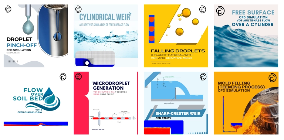
Figure 15:Related CFD products for ANSYS Fluent VOF. These tutorials help users learn droplet breakup, microdroplet formation, slug flow, bubble growth, and multiphase flow setup.
The first useful product is Droplet Pinch-Off CFD Simulation: ANSYS Fluent Tutorial. This tutorial shows capillary thinning and droplet breakup. It is useful for learning Surface Tension Modeling, Capillary Effects in CFD, and interface deformation in ANSYS Fluent VOF.
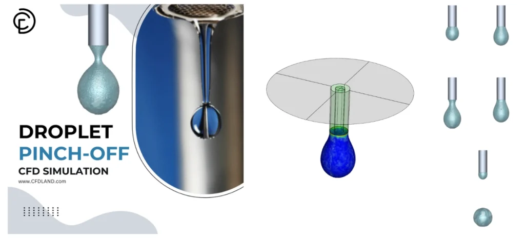
Figure 16: Product cover for Droplet Pinch-Off CFD Simulation. This tutorial helps users study capillary thinning, surface tension, and droplet breakup in ANSYS Fluent.:
Another related product is Microdroplet Generation CFD Analysis: VOF Simulation in a T-Junction using ANSYS Fluent. This case models droplet formation in a microchannel. It helps users learn VOF Simulation, phase interaction, surface tension force, and droplet motion.
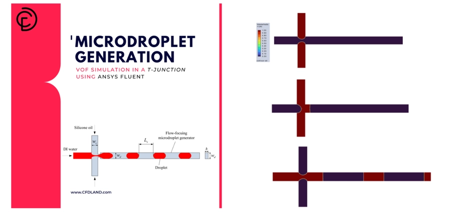
Figure 17: Product cover for Microdroplet Generation CFD Analysis. This tutorial shows droplet formation and interface tracking in a T-junction microchannel.
The next product is Slug Flow in Capillary Microreactor CFD Simulation ANSYS Fluent Training. This tutorial is useful for users who work with small channels. It shows liquid-gas slug flow, interface motion, and multiphase flow patterns in a capillary microreactor.
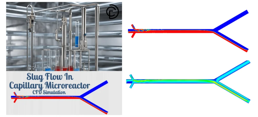
Figure 18: Product cover for Slug Flow in Capillary Microreactor. This training helps users learn liquid-gas interface tracking and VOF setup in small channels.
The last recommended product is Isolated Bubble CFD Simulation in Nucleate Boiling: A VOF Mass Transfer Fluent Tutorial. This tutorial shows bubble growth in nucleate boiling. It is useful for learning VOF, mass transfer, phase change, and bubble interface tracking.
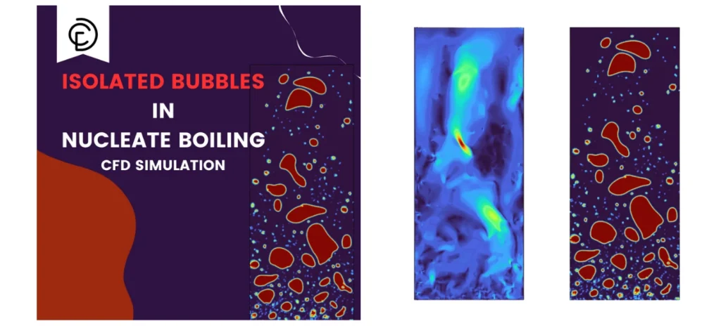
Figure 19: Product cover for Isolated Bubble CFD Simulation in Nucleate Boiling. This tutorial helps users study bubble growth, VOF mass transfer, and phase change in ANSYS Fluent.
These products are practical examples. They help users understand ANSYS Fluent Multiphase, CFD Surface Tension, droplet breakup, slug flow, and bubble motion in real CFD models.
Common Problems and Best Practices in VOF Simulation
A VOF Simulation can be sensitive. Small errors can change the interface shape. They can also change droplet size, wall wetting, and breakup time. So, the user must check the model before the final run.
In ANSYS Fluent VOF, many problems come from mesh, time step, material data, and interface settings. The Volume Fraction Equation needs a stable setup. If not, the Liquid-Gas Interface can become too thick or unstable.
The best VOF result needs correct mesh, small time step, correct surface tension, and correct contact angle.
The table below shows common problems in ANSYS Fluent Multiphase modeling.
Table 4: common problems in ANSYS Fluent Multiphase modeling
| Problem | Main Cause | Simple Fix |
| Interface smearing | Coarse mesh or large time step | Refine mesh and reduce time step |
| Wrong droplet shape | Wrong Surface Tension Coefficient | Check fluid pair data |
| Wrong wall wetting | Wrong contact angle | Check Wall Adhesion Boundary Condition |
| Spurious currents | Poor mesh near interface | Improve mesh quality |
| Poor convergence | Large time step or bad cells | Use smaller time step and better mesh |
| Wrong capillary motion | Weak surface tension setup | Check CSF Model and phase interaction |
For Troubleshooting surface tension in Fluent VOF, the user should first check the Surface Tension Coefficient. Then, the user should check the mesh near the interface. This is important because the Continuum Surface Force Model uses the interface shape to apply force.
For Contact Angle CFD, the user must check the wall zone. The contact angle must be set on the correct wall. This is the main point in Wall adhesion setup in ANSYS Fluent. It is also important for Wetting Behavior Simulation.
If the model has small channels, droplets, or thin films, Capillary Effects in CFD can be strong. In this case, the user must use a fine mesh and a small time step. This helps answer How to simulate capillary effects in ANSYS Fluent.
For Free Surface Flow Simulation, gravity can also be important. The user must check if gravity is active and set in the correct direction.
In short, Best practices for VOF simulation in Fluent are simple. Use clean geometry. Use good mesh. Use correct material data. Use correct CFD Surface Tension settings. Use correct wall adhesion. Also, keep the time step small enough.
A stable Fluent VOF Setup is the key to a clear interface, correct wall wetting, and reliable multiphase flow results.
Conclusion
A correct VOF Simulation needs more than one setting. The user must check the model, phases, mesh, time step, Surface Tension Coefficient, and wall contact angle together. In ANSYS Fluent VOF, all these items affect the Liquid-Gas Interface.
The CSF Model or Continuum Surface Force Model uses the interface shape to calculate CFD Surface Tension force. So, a weak mesh can create a weak result. Also, a wrong contact angle can give wrong Wetting Behavior Simulation near the wall.
For a reliable ANSYS Fluent Multiphase result, surface tension, contact angle, mesh, and time step must work together.
Table 5: The most important items of ANSYS Fluent for VOF simulation
| Check Item | Why It Is Important |
| VOF Model | It tracks the interface between phases. |
| Material Properties | Density and viscosity affect flow motion. |
| Surface Tension Coefficient | It controls interface force and droplet shape. |
| Wall Adhesion Boundary Condition | It defines contact angle and wall wetting. |
| Mesh Quality | It helps reduce spurious currents. |
| Time Step | It helps improve transient stability. |
This article can be used as a simple VOF surface tension modeling guide. It helps users understand How to model surface tension in Fluent VOF, How to define surface tension coefficient in Fluent, and How to set up contact angle in ANSYS Fluent.
For difficult cases, users should also check common problems. These include unstable interface motion, wrong droplet shape, poor wall wetting, and false small velocities. These points are part of Troubleshooting surface tension in Fluent VOF.
In short, Best practices for VOF simulation in Fluent are clear. Use a clean geometry. Use a good mesh. Use correct phase data. Use a small enough time step. Set Wall Adhesion in ANSYS Fluent with the right contact angle. Then check the result step by step.